Solid particle pre-whirl mixing pneumatic acceleration device and method

A technology of solid particles and acceleration device, applied in the direction of liquid injection device, injection device, etc., can solve the problem of reducing the accuracy of material erosion test, and achieve the effect of improving consistency and uniformity

Inactive Publication Date: 2015-05-27
XI AN JIAOTONG UNIV
View PDF7 Cites 0 Cited by
  • Summary
  • Abstract
  • Description
  • Claims
  • Application Information

AI Technical Summary

Problems solved by technology

It is well known that this will change the contact angle of the particle with the surface of the test piece, which in turn will greatly reduce the accuracy of the material erosion test

Method used


Image

  • Solid particle pre-whirl mixing pneumatic acceleration device and method
  • Solid particle pre-whirl mixing pneumatic acceleration device and method
  • Solid particle pre-whirl mixing pneumatic acceleration device and method

Examples


Embodiment 1

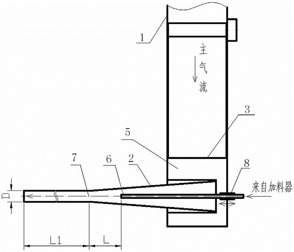
[0035] see image 3 , Figure 4 , a solid particle pre-swirling mixing pneumatic acceleration device, including an air inlet pipe 1 and an acceleration nozzle 2 connected to the air inlet pipe 1, the connection between the acceleration nozzle 2 and the air inlet pipe 1 is provided with a gas flow that enters the acceleration nozzle 2 The airflow pre-swirling device that generates the swirling flow, the airflow pre-swirling device is the deflector 3 arranged in the intake pipe 1, the deflector 3 and the wall of the intake pipe 1 are formed so that the airflow flows into the inlet of the acceleration nozzle 2 along the tangential direction The wedge-shaped flow channel, the deflector 3 can be rotated, and the side wall of the intake pipe 1 is inwardly recessed to form a groove. It is connected to the air outlet at the bottom of the groove. The function of the ring cavity is to stabilize the air flow on the one hand and assist the generation of swirling flow on the other hand. T...

Embodiment 2

[0039] see Figure 5 , Image 6 , a solid particle pre-swirling mixing pneumatic acceleration device, including an air inlet pipe 1 and an acceleration nozzle 2 connected to the air inlet pipe 1, the connection between the acceleration nozzle 2 and the air inlet pipe 1 is provided with a gas flow that enters the acceleration nozzle 2 An airflow pre-swirling device for generating swirling flow, the airflow pre-swirling device is a swirler 4 arranged at the inlet of the acceleration nozzle 2, and the swirler 4 includes 5 (preferably 3 to 8) guide vanes, the exhaust angle is 60° (the value range is 35°~80°), one side of the inlet pipe 1 is sunken inward to form a groove, and the groove divides the inside of the inlet pipe into a ring cavity 5, and the inlet of the acceleration nozzle 2 is connected with the opening It is connected to the air outlet at the bottom of the groove. The function of the ring cavity is to stabilize the air flow on the one hand and assist the generation ...


PUM


Abstract

The invention discloses a solid particle pre-whirl mixing pneumatic acceleration device and method. An acceleration nozzle is of a contraction-straight pipe type or scaling type; the primary air flow generates moderate rotational flow before entering the acceleration nozzle through a specially-designed cyclone or a similar device; the solid particles are directly sprayed to the front part of the nozzle throat in an air flow carrying mode; the solid particles sprayed from a thin pipe are accelerated along the flow direction while generating radial diffusion under the dragging of the rotating air flow; the rotation kinetic energy of the air flow can be gradually dissipated under the mutual effect between the wall surface and the solid particles; the space distribution of the particles is dissipated along with the rotational flow and tends to be stable; and finally, a uniform high-speed air-solid two-phase jet flow is formed. The device and method disclosed by the invention can be used for improving the uniformity of the space distribution of the particles and the speed consistency of the particles, and are of great significance in improving the technology quality of the industrial production of a material thermal spraying technology, sand blasting and the like and improving the test precision of the scientific research field of solid particle erosion acceleration test and the like.

Description

technical field [0001] The invention relates to a method for rapidly aerodynamically mixing and dispersing particles during the aerodynamic acceleration process of solid particles, in particular to a solid particle pre-spinning aerodynamic acceleration device and method. Background technique [0002] Pneumatic acceleration devices for solid particles are often composed of a feeding system, an air source, and an acceleration nozzle. Accelerated and mixed under the drag of the air force, and finally form a high-speed gas-solid two-phase jet. Similar methods and devices are widely used in industrial production and scientific research fields such as material thermal spraying technology, sand blasting treatment, and accelerated erosion test of solid particles. [0003] However, limited by the length of the aerodynamically accelerated diffusion section and the method of particle addition, problems such as particle concentration and uneven spatial distribution often occur, which s...

Claims


Application Information

Patent Timeline
Patent Type & Authority Patents(China)
IPC IPC(8): B05B7/14
Inventor 王顺森毛靖儒蔡柳溪张磊
Owner XI AN JIAOTONG UNIV
Why Eureka
Try Eureka