
Travelling frame

A technology of frame and road wheel, applied in axles, wheels, vehicle parts, etc., can solve the problems of high cost, complex structure of road wheel shock absorber system, difficult maintenance, etc., and achieve the effect of simple structure

Inactive Publication Date: 2012-10-24
LIUZHOU ANLONG MACHINERY EQUIP
View PDF3 Cites 3 Cited by
  • Summary
  • Abstract
  • Description
  • Claims
  • Application Information

AI Technical Summary

Problems solved by technology

[0003] The technical problem to be solved by the present invention is to provide a walking frame, which can solve the problems of complex structure, high cost and difficult maintenance of the traveling wheel shock absorber system of mobile machinery and equipment

Method used


Image

  • Travelling frame
  • Travelling frame
  • Travelling frame

Examples


Embodiment Construction

[0014] Below in conjunction with accompanying drawing and embodiment the present invention is further described:

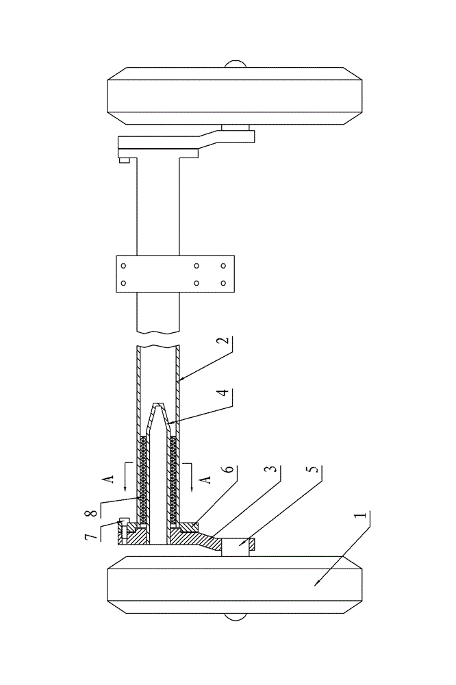
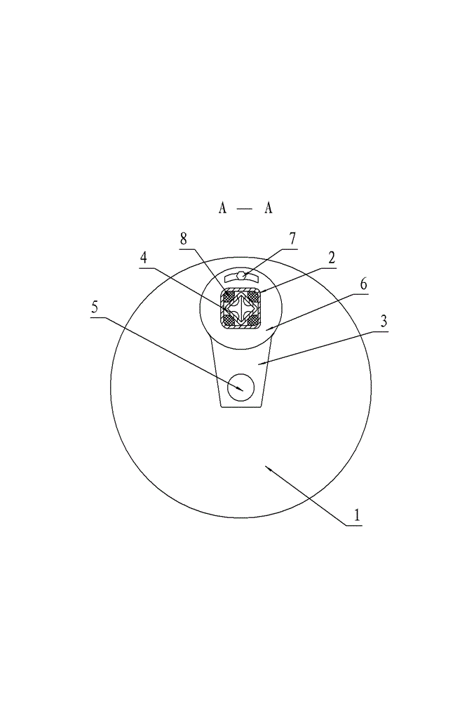
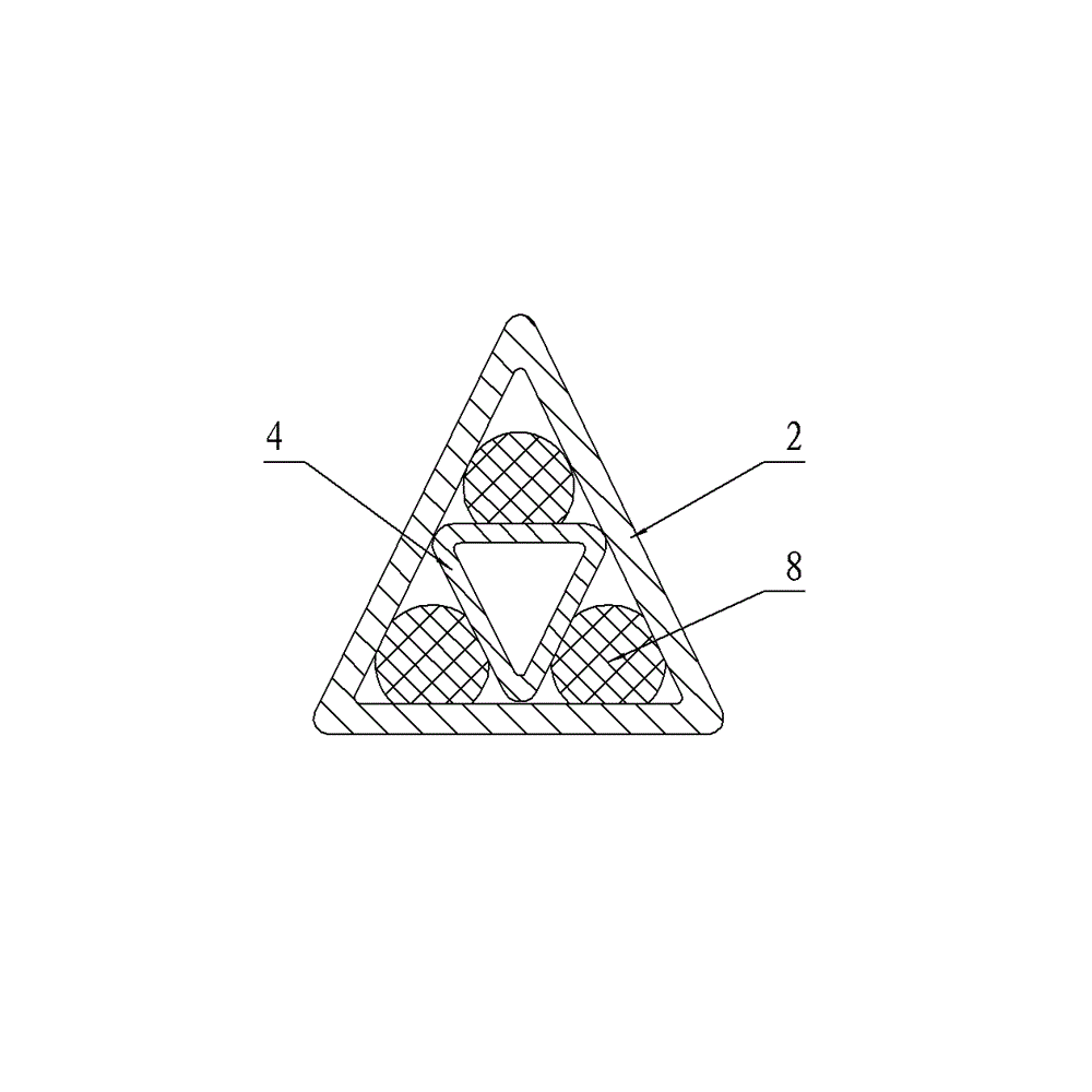
[0015] figure 1 with figure 2 The traveling vehicle frame shown includes a traveling wheel 1 and a vehicle beam 2 . The vehicle beam 2 is a square tube body, the wheel shaft 5 of the road wheel 1 is connected with one end of the swing arm 3, and the upper end of the swing arm 3 is fixedly connected with the vehicle beam 2 through the flange 6 connected with the end of the vehicle beam 2 with a screw 7, The screw 7 has the upper and lower dead points for controlling the swing of the wheel; the other end of the swing arm 3 is connected with the shaft core 4 in the vehicle beam 2, and the shaft core 4 is also a square tube, and the four corners of the shaft core 4 square tube are placed At the midpoint of the four sides of the inner wall of the square tube of the vehicle beam 2; the shaft core 4 is rotatable relative to the tube wall of the vehicle beam 2; four e...


PUM


Abstract

The invention relates to the technical field of mechanical manufacturing and discloses a travelling frame. The travelling frame comprises a travelling wheel and a vehicle frame, wherein a wheel shaft of the travelling wheel is connected with one end of a swing arm and the other end of the swing arm is fixedly connected with the vehicle beam through a flange; one end of the swing arm, which is fixedly connected with the flange, is further hinged with a core shaft; the core shaft is placed in one section of holes at the two ends of the vehicle frame; at least one of the core shaft and the cross section of one part of the vehicle beam, which has the holes, is a non-circular section; a gap between the core shaft and the inner wall of the hole of the vehicle beam is filled with an elastic body; and the elastic body is a fluorine-containing rubber cylinder. According to the travelling frame disclosed by the invention, a shock-proof system of the travelling wheel of movable machine equipment solves the problems of complicated structure, high cost and difficulty in maintenance.

Description

technical field [0001] The invention relates to the technical field of mechanical manufacturing, in particular to a vehicle frame for placing mobile machinery and equipment. Background technique [0002] At present, mobile air compressors, generator sets and some small engineering machinery and equipment are often used in mines or relatively remote engineering construction sites. When moving, these mechanical equipment bump and vibrate along the front, rear, left and right directions. In order to achieve shock absorption, for these non-steering road wheel shock absorber systems, the conventional practice is to use automobile shock absorber springs to overlap and install on the frame axle. The running speed generally does not exceed 40 kilometers per hour, and there are not many cases of walking for a long time, so the use of automobile shock absorber springs is sufficient to meet the shock absorber requirements of these mobile machines, but its disadvantage is that the thic...

Claims


Application Information

Patent Timeline
IPC IPC(8): B62D21/00B60B35/00B60B37/06
Inventor 唐振荣
Owner LIUZHOU ANLONG MACHINERY EQUIP
Learn More