Method and apparatus for adjusting ejection angle position of sub-nozzle in an air jet loom

A jet angle and air jet technology, applied in looms, textiles, papermaking, textiles, etc., can solve the problems of inability to make precise adjustments, and the inability to adjust the position of the nozzle jetting angle, achieve easy setting and operation, and reduce the process and time. , the effect of improving quality

Active Publication Date: 2012-10-24
TSUDAKOMA KOGYO KK
View PDF8 Cites 14 Cited by
  • Summary
  • Abstract
  • Description
  • Claims
  • Application Information

AI Technical Summary

Problems solved by technology

[0010] However, in the prior art described in Patent Document 1, when adjusting the spray angle position of the sub-nozzles, it is only possible to adjust all the sub-nozzles simultaneously and with the same adjustment amount, or to adjust the yarn-feeding side and the reverse yarn-feeding side divided int

Method used


Image

  • Method and apparatus for adjusting ejection angle position of sub-nozzle in an air jet loom
  • Method and apparatus for adjusting ejection angle position of sub-nozzle in an air jet loom
  • Method and apparatus for adjusting ejection angle position of sub-nozzle in an air jet loom

Examples


Embodiment Construction

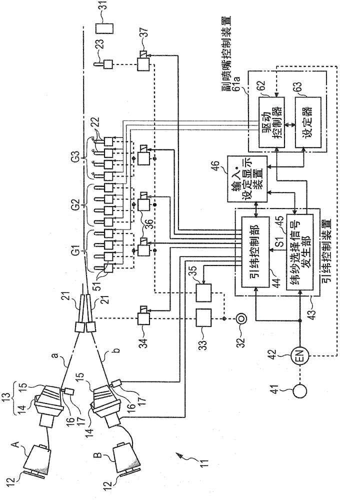
[0049] figure 1 As an example of an air jet loom to which the present invention is applied, main parts of a loom including a multi-color weft insertion device are shown. exist figure 1 In the figure, the two-color weft insertion device 11 that inserts two kinds of weft yarns (the weft yarn a wound on the yarn supply body A, and the weft yarn b wound on the yarn supply body B) is shown, and the two-color weft insertion device 11 corresponds to the multi-color weft insertion device of the present invention.

[0050] exist figure 1 In the weft insertion device 11, the weft yarn a and the weft yarn b are drawn from the yarn supply body A or B supported by each yarn supply body frame 12, and introduced into the yarn winding of the drum type length measuring weft storage device 13, for example. The inside of the arm 14 is wound around the outer peripheral surface of the drum 15 by the rotational movement of the yarn winding arm 14 while the outer peripheral surface of the drum...


PUM


Abstract

The invention disclsoes a method and an apparatus for adjusting an ejection angle position of a sub-nozzle in an air jet loom, and particulalry aims to provide a method and an apparatus for finely adjusting an ejection angle position of a sub-nozzle in accordance with a weaving state. The air jet loom includes a plurality of sub-nozzles arranged along a weft insertion path and a plurality of electromagnetic on-off valves provided to supply compressed air to the sub-nozzles, each electromagnetic on-off valve being connected to one or more of the sub-nozzles, the sub-nozzles connected to each electromagnetic on-off valve ejecting the air to perform weft insertion. The method includes the steps of driving one or more sub-nozzles that belong to an adjustment unit with at least one actuator the adjustment unit including at least one of the one or more sub-nozzles connected to at least one of the electromagnetic on-off valves, and adjusting an ejection angle position of each sub-nozzle included in the adjustment unit by the same angle.

Description

technical field [0001] The present invention relates to an air-jet loom, especially one having a plurality of sub-nozzles arranged along a weft insertion path, and one or more sub-nozzles provided for supplying compressed air to the sub-nozzles and each connected to one or more sub-nozzles A plurality of electromagnetic switching valves, in each of the electromagnetic switching valves, the secondary nozzles perform air injection to insert weft yarns in an air jet loom, a method and device for adjusting the injection angle position of the secondary nozzles. Background technique [0002] The so-called "injection angular position" in this application refers to the angular position of the air injection opening around the axis of the sub-nozzle relative to the axis, more specifically, as Figure 7 As shown, looking at the sub-nozzle 22 from above, it is an angle formed by a straight line connecting the axis and the air injection port (the center of the air injection port) 22a with...

Claims


Application Information

Patent Timeline
IPC IPC(8): D03D47/30D03D51/00
CPCD03D47/304D03D47/302
Inventor 北浩一松山丰
Owner TSUDAKOMA KOGYO KK
Why Eureka
Try Eureka