Jet flow rotor gyroscope based on expansion-shrinkage pipe micropump

A jet rotor and shrink tube technology, applied in the field of inertial measurement, can solve the problems of temperature rise, affecting the detection accuracy of jet rotor gyroscope, and the vibration cavity cannot complete alternate air injection and suction, etc.

Inactive Publication Date: 2012-10-24
NORTHWESTERN POLYTECHNICAL UNIV
View PDF3 Cites 4 Cited by
  • Summary
  • Abstract
  • Description
  • Claims
  • Application Information

AI Technical Summary

Problems solved by technology

[0005] However, this gyro is a closed system
In a closed system, due to the complexity of the airflow movement, although the phase difference between the excitation voltages of the two piezoelectric sheets is π, the two vibrating chambers cannot complete alternate air injection and suction, and it is difficult to realize the directional movement of the airflow
Because the two vibrating chambers have different

Method used


Image

  • Jet flow rotor gyroscope based on expansion-shrinkage pipe micropump
  • Jet flow rotor gyroscope based on expansion-shrinkage pipe micropump
  • Jet flow rotor gyroscope based on expansion-shrinkage pipe micropump

Examples


Embodiment Construction

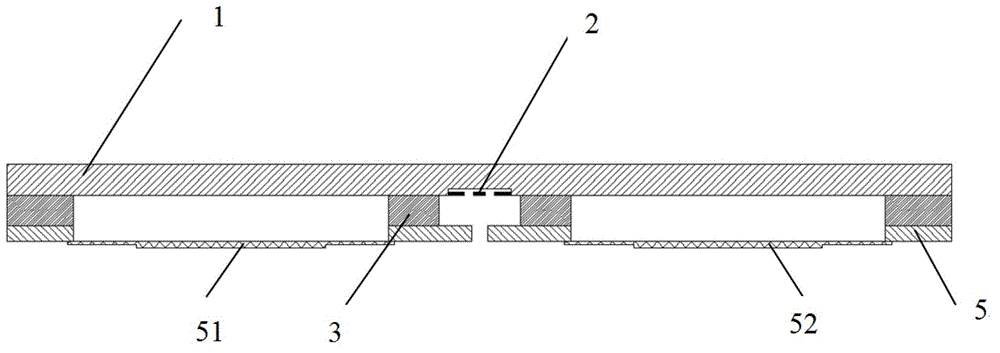
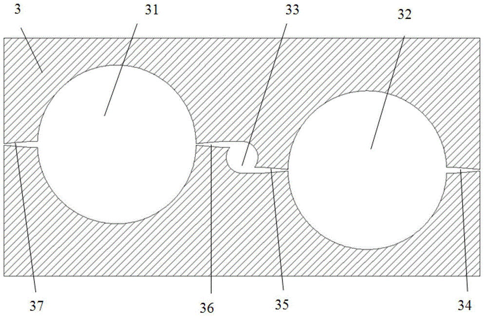
[0019] refer to Figure 1-6 , a jet rotor gyroscope based on an expanding-shrinking tube micropump, refer to Figure 1-5 , including an upper sealing layer 1, a thermistor layer 2, a cavity layer 3 and a lower sealing layer 5 in turn; the cavity layer 3 has a through cylindrical cavity, and vibrations are evenly distributed in the outer circumferential direction of the cylindrical cavity Cavity I31 and vibration cavity II32; both vibration cavity I31 and vibration cavity II32 do not penetrate the cavity layer 3, and the parts that do not penetrate form corresponding vibrating films respectively; each vibrating film is connected with a piezoelectric film I51 and a piezoelectric film II52; the cylindrical cavity communicates with the vibration chamber I31 and the vibration chamber II32 through the air outlet I35 and the air outlet II36 respectively; the air outlet I35 and the air outlet II36 are radially staggered; the air outlet I35 and the air outlet II36 are both tapered The...


PUM


Abstract

The invention relates to a jet flow rotor gyroscope based on an expansion-shrinkage pipe micropump, which belongs to the field of inertia measurement. The detection cavity of the jet flow rotor gyroscope is respectively communicated with a corresponding vibration cavity by a corresponding air outlet; each air outlet is radially staggered; the air outlet is a taper-shaped channel; the small end of the air outlet is connected with the detection cavity; the big end of the air outlet is connected with the vibration cavity; meanwhile, the vibration cavity is communicated with outside by a taper-shaped air inlet; a small taper-shaped end is connected with the outside; and a big end is connected with the vibration cavity. According to the jet flow rotor gyroscope based on the expansion-shrinkage pipe micropump, which is disclosed by the invention, the characteristics of synthetic jet flow are fully utilized, the directed transmission and the unidirectional flow of air, i.e. transmission and flow from the air inlet to the air outlet as well as from the vibration cavity to the detection cavity, are realized by different resistances on an airflow on the air inlet and the air outlet. The jet flow rotor gyroscope is communicated with outside via air vents so as to solve air temperature rise caused by piezoelectric sheet vibration and improve the precision of the jet flow rotor gyroscope. When the vibration phase difference of the vibration cavities is zero, a generated airflow rotor shaft has a better consistency with a shell shaft.

Description

technical field [0001] The invention relates to a jet rotor gyroscope based on an expansion-contraction tube micropump, which belongs to the field of inertial measurement. Background technique [0002] The expansion-contraction tube micropump utilizes the fluid resistance characteristics of the contraction tube / expansion tube to realize the directional delivery of the fluid. In the field of flow control, such as flow separation and aerodynamic control, jet vector control, enhanced mixing and heat and mass transfer control, micro Fluid transmission and control have very broad application prospects. [0003] The basic principle of the jet rotor gyro is that the gas ejected by the micropump forms a gas flow rotor in the detection chamber, and the jet rotor has the fixed axis and precession of the traditional mechanical rotor. When there is an input of angular velocity or acceleration perpendicular to or parallel to the rotation axis of the fluid rotor, the thermistor fixed to ...

Claims


Application Information

Patent Timeline
IPC IPC(8): G01C19/02
Inventor 常洪龙周平伟杨勇郝永存洪水金谢建兵袁广民
Owner NORTHWESTERN POLYTECHNICAL UNIV
Why Eureka
Try Eureka