Blind zone optimized progressive eye lens and mold thereof

A technology for ophthalmic lenses and blind areas, which is applied in glasses/goggles, optics, instruments, etc., can solve problems such as the position and size of astigmatism in blind areas that are not explained, and achieve improved fusion effects, improved comfort, and reduced deformation Effect

Inactive Publication Date: 2012-10-24
苏州苏大明世光学股份有限公司
View PDF8 Cites 3 Cited by
  • Summary
  • Abstract
  • Description
  • Claims
  • Application Information

AI Technical Summary

Problems solved by technology

[0014] Chinese patent CN102043258A discloses a method for optimizing the astigmatism of a progressive multifocal ophthalmic lens. Through the optimization steps of the invention, the maximum astigmatism on the surface of the initially d

Method used


Image

  • Blind zone optimized progressive eye lens and mold thereof
  • Blind zone optimized progressive eye lens and mold thereof
  • Blind zone optimized progressive eye lens and mold thereof

Examples


Embodiment 1

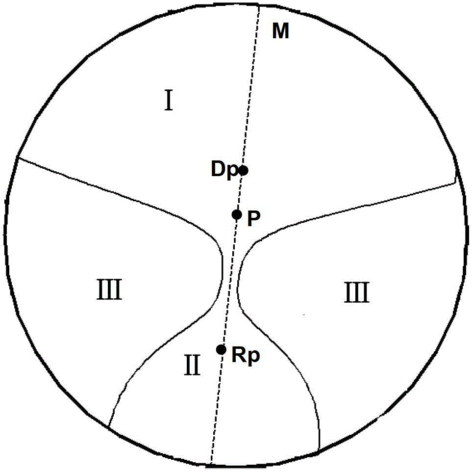
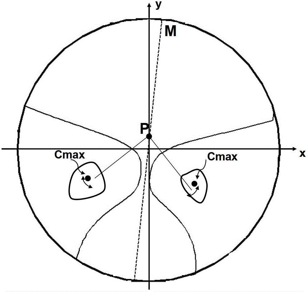
[0038] Consider a lens with a freeform surface facing object-space space and a spherical or cylindrical surface facing the wearer of the spectacle, the outer progressive ophthalmic lens. A lens suitable for the right eye is considered here, and a lens suitable for the left eye can be obtained by simply taking the mirror image of the lens of the right eye. The processing surface is the outer surface of the lens, which is a convex free-form surface with a power and a cylinder at each point, and the diameter of the lens is 72mm.

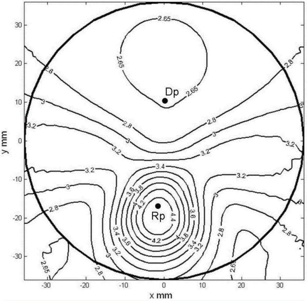
[0039] image 3It shows the isofocal power contour map of this surface, which is precisely the projection of the power distribution of the freeform surface on the outer surface of the lens on the plane. exist image 3 The upper part of the lens has a broad focal power stabilization zone called the far zone. As a reference point, the far point Dp is in the far zone. The focal power value of the far point is 2.65D. image 3 The lower part of the lens ...

Embodiment 2

[0044] The biggest difference from Embodiment 1 is that the lens in this example has a spherical or cylindrical surface facing the object space and a free-form surface facing the wearer of the glasses, that is, the inner progressive ophthalmic lens. The machined surface is the inner surface of the lens, which is a concave, free-form surface with one power and one cylinder at each point. The power of a lens is made up of the powers of the inner and outer sides. Specifically, the optical power of the lens is approximately equal to the optical power of the outer surface minus the optical power of the inner surface. A progressive lens with addition, if its free-form surface is designed on the inner surface of the lens, its addition will be negative. That is to say, the focal power of the free-form surface in this example has the feature of light reduction from top to bottom.

[0045] For this example consider a lens suitable for the left eye with a lens diameter of 70 mm. As me...


PUM

PropertyMeasurementUnit
Diameteraaaaaaaaaa
Optical poweraaaaaaaaaa

Abstract

The invention relates to a blind zone optimized progressive eye lens for and a mold thereof. The blind zone optimized progressive eye lens comprises a lens surface with certain radian, a far sight zone, a near sight zone, a channel, a left blind zone and a right blind zone, the cylindrical surface degree of the blind zones with maximum astigmatism is lower than the lighting degree of the lens, the maximum value of the cylindrical surface degree is controlled to be lower than 96% of the lighting degree value, and the distance of maximum astigmatism in the horizontal direction is greater than 22 mm. The cylindrical surface degree of the blind zones with maximum astigmatism is lower than the lighting degree and the position of the maximum value of the cylindrical surface degree is far away from the lens dispensing center, so that the sense of deformation of the middle distance is ensured to decline when a wearer looks at static objects or dynamic objects. The progressive lens disclosed by the invention can be applied to molded external progressive eye lenses, and can also be applied to internal progressive eye lenses manufactured in a free-from surface garage. The invention further relates to a glass mold or a metal mold for molded internal surface progressive eye lenses or external surface progressive eye lenses formed by hot melting or manufactured by the free-from surface grinding method.

Description

technical field [0001] The invention relates to the technical field of multifocal ophthalmic lenses. Specifically, the present invention relates to a progressive multifocal spectacle lens and a mold thereof whose blind spot is relatively far from the center of dispensing glasses and has a reduced sense of deformation at mid-distance. Background technique [0002] Progressive addition ophthalmic lenses are used to correct refractive errors. When the wearer observes distant objects through the upper part of the lens, it corrects the distance vision ability of the human eye in a relaxed state of vision. The line of sight through the lower part of the lens can be used to correct near-sightedness under close viewing conditions. [0003] Progressive multifocal ophthalmic lenses provide distance vision and near vision power on the same lens. At the same time, the surface shape of the lens is naturally connected. There is no breakage in visual objects, which is both beautiful and...

Claims


Application Information

Patent Timeline
IPC IPC(8): G02C7/06G02C7/02
Inventor 陈晓翌余浩墨
Owner 苏州苏大明世光学股份有限公司
Why Eureka
Try Eureka