Mesh layout method for simulating deformation of free surfaces of rubber spherical hinge

A technology for simulating rubber and rubber ball joints, applied in special data processing applications, instruments, electrical digital data processing, etc. question

Inactive Publication Date: 2015-02-25
ZHUZHOU TIMES NEW MATERIALS TECH
View PDF3 Cites 0 Cited by
  • Summary
  • Abstract
  • Description
  • Claims
  • Application Information

AI Technical Summary

Problems solved by technology

[0005] However, the grids divided by the existing technology are only based on the shape characteristics of the fitting model, and are not laid out according to the bearing and force characteristics of the model. Therefore, the existing grid layout method can only reflect the shape characteristics of the model, and does not It cannot reflect the load-bearing characteristics of the model structure, which leads to the fact that during the simulation process, the elements in some local areas on the surface of the rubber spherical joint tend to be highly twisted and deformed due to the free surface, causing large deformation of the element itself and resulting in a certain part of the element The node penetrates the surface of the unit to which it belongs, and even abnormal deformation phenomena such as self-locking occur, which eventually makes the analysis impossible, that is, the simulation of the deformation of the free surface of the rubber ball joint cannot be completed, and it is impossible to ensure that the rubber ball joint is deformed during the loading process. Always maintain a state of compressive stress

Method used


Image

  • Mesh layout method for simulating deformation of free surfaces of rubber spherical hinge
  • Mesh layout method for simulating deformation of free surfaces of rubber spherical hinge
  • Mesh layout method for simulating deformation of free surfaces of rubber spherical hinge

Examples


Embodiment Construction

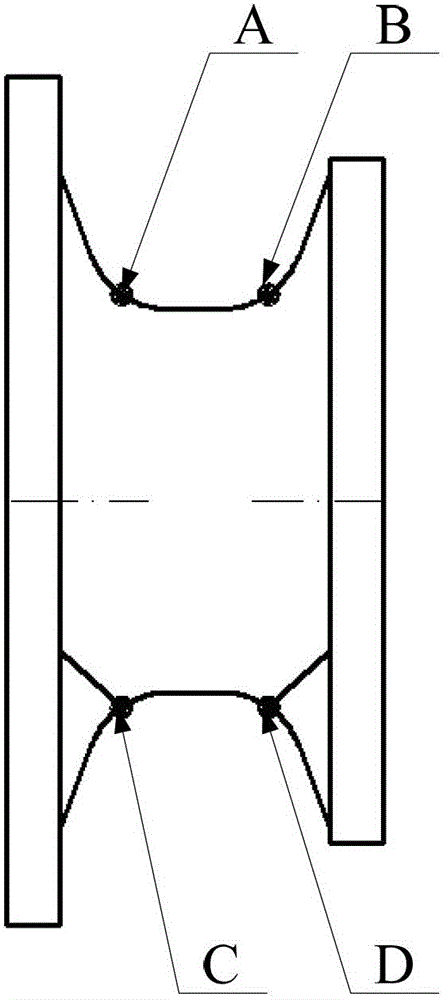
[0029] The following will clearly and completely describe the technical solutions in the embodiments of the present invention with reference to the accompanying drawings in the embodiments of the present invention. Obviously, the described embodiments are only some, not all, embodiments of the present invention. Based on the embodiments of the present invention, all other embodiments obtained by persons of ordinary skill in the art without making creative efforts belong to the protection scope of the present invention.

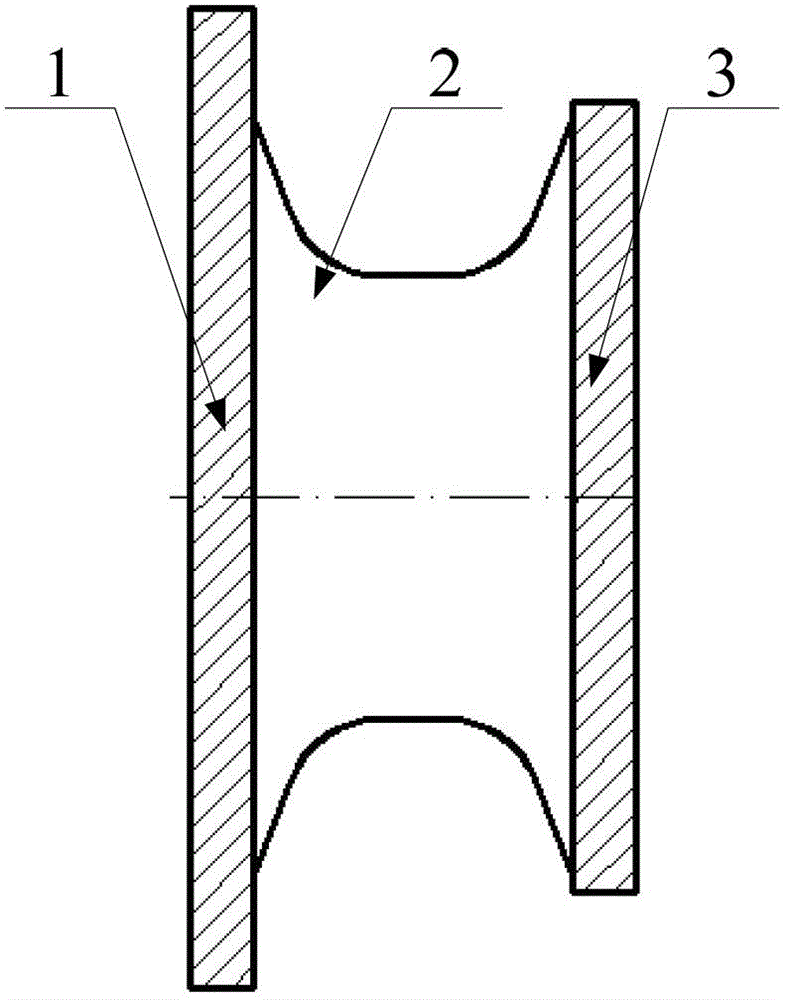
[0030] In this paper, the free edge of the end zone refers to the edge of rubber 2 not connected with inner iron part 1 and outer iron part 3 in the rubber ball hinge model; the non-free edge of the end zone refers to the edge of rubber The side where the inner iron part 1 or the outer iron part 3 is connected.

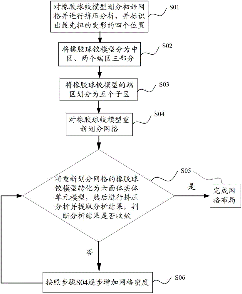
[0031] Please refer to the attached Figure 1-Figure 9 , the present invention provides a grid layout method for simulating the deformation of the r...


PUM


Abstract

The invention provides a mesh layout method for simulating deformation of free surfaces of a rubber spherical hinge. The method includes marking out a position where distortion emerges first through initial mesh division and extrusion analysis and performing vertical subdivision at the position so as to guide further emerging distortion; dividing a rubber spherical hinge model into a central area and an end area through a main subdivision line and dividing the end area into five sections through a main depth subdivision line and an auxiliary depth subdivision line; and performing meshing on request at last, performing parameterization configuration on the meshes along with surface depth, laying out meshes in a suitable quantity on each free surface, and finishing the mesh layout through regulation of the mesh density. According to the mesh layout method, shape features and loading characteristics of the free surfaces of the rubber spherical hinge are reflected by the divided meshes, therefore mesh setting requirements in a high distortion area can be satisfied, stress results of the high distortion area is predicted accurately, and a premise is provided for finishing the deformation simulation of the free surfaces of the rubber spherical hinge.

Description

technical field [0001] The invention relates to the technical field of grid layout for finite element analysis simulating the deformation of the free surface of a rubber ball joint, and more specifically relates to a grid layout method for simulating the deformation of the free surface of a rubber ball joint. Background technique [0002] As a connecting joint, the rubber ball joint can provide degrees of freedom and deformation in six directions, and is widely used in the fields of construction machinery, railways and ships. In actual use, the fatigue life of the rubber ball joint needs to meet certain requirements. At present, in order to improve the fatigue life of the rubber ball joint, the rubber ball joint is squeezed to a certain extent before use, and then the motion state of the rubber ball joint is simulated through the analysis software to ensure that the rubber ball joint is Always maintain a state of compressive stress. [0003] At present, the simulation of t...

Claims


Application Information

Patent Timeline
Patent Type & Authority Patents(China)
IPC IPC(8): G06F17/50
Inventor 黄友剑王宏
Owner ZHUZHOU TIMES NEW MATERIALS TECH
Why Eureka
Try Eureka