Construction method of three-dimensional tunnel group structure

A technology of tunnel structure and construction method, which is applied in the direction of basic structure engineering, underwater structures, excavation, etc. It can solve the problems of difficult construction of airport passages, passages cannot be arranged side by side, and slow construction speed, so as to reduce construction costs and improve construction efficiency. Efficiency and space-saving effect

Active Publication Date: 2020-04-07
CHINA RAILWAY NO 2 ENG GRP CO LTD +1
View PDF6 Cites 0 Cited by
  • Summary
  • Abstract
  • Description
  • Claims
  • Application Information

AI Technical Summary

Problems solved by technology

[0006] The purpose of the present invention is: for the prior art: all passages entering the airport cannot be arranged side by side, which brings great difficulties for the construction of the airport passages; To solve the problem of low efficiency, a construction method of a three-dimensional tunnel group structure is provided. By arranging multiple tunnels in space, a three-dimensional tunnel group is formed to ensure the construction progress while meeting the requirements for the use of passages.

Method used


Image

  • Construction method of three-dimensional tunnel group structure
  • Construction method of three-dimensional tunnel group structure
  • Construction method of three-dimensional tunnel group structure

Examples


Embodiment 1

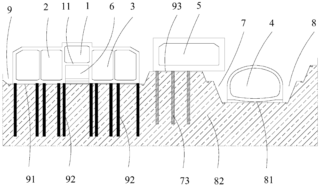
[0125] like figure 1 and 11 As shown, a construction method of a three-dimensional tunnel group structure comprises the following steps:

[0126] S1. Excavating the first foundation pit 9 to the first bottom surface 91;

[0127] S2. setting a plurality of first support piles 92 on the first bottom surface 91;

[0128] S3. Carry out the construction of the first tunnel structure 1, the second tunnel structure 2 and the third tunnel structure 3 on the first support pile 92, wherein, between the second tunnel structure 2 and the third tunnel structure 3 A first bottom plate 11 is connected, and the first bottom plate 11, the second tunnel structure 2 and the third tunnel structure 3 form a first tunnel structure 1 and a first cavity 6, and the first cavity 6 is located in Below the first bottom plate 11;

[0129] S4. After the construction of the first tunnel structure 1, the second tunnel structure 2 and the third tunnel structure 3 is completed, the first cavity 6 is backfi...

Embodiment 2

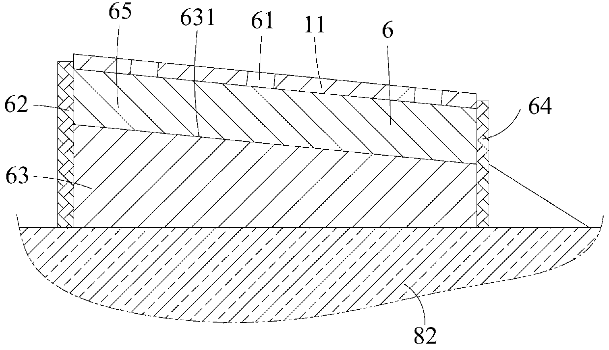
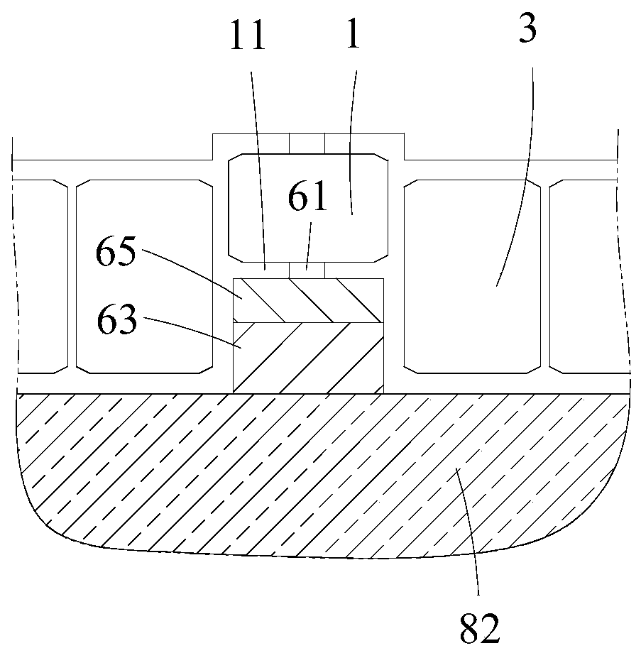
[0139] like Figure 2-4 As shown, the construction method of a three-dimensional tunnel group structure described in this embodiment is different from Embodiment 1 in that one end of the first cavity 6 is sealed and connected with a first sealing wall 62, and the The other end of the first cavity 6 is sealed and connected with a second sealing wall 64, and a top backfill layer structure 65 and a bottom backfill layer structure 63 are arranged in the first cavity 6 from top to bottom, and the top backfill layer structure 65 and the bottom backfill layer structure 63 jointly fill the first cavity 6, the top backfill layer structure 65 is made of self-compacting material filling, and the bottom backfill layer structure 63 has a 65 in contact with the first top surface 631, there is a first gap between the first top surface 631 and the first bottom plate 11, the first bottom plate 11 is provided with at least one cavity 6 It is connected to the inlet 61 through which the filler o...

Embodiment 3

[0151] like Figure 5-8 As shown, the construction method of a three-dimensional tunnel group structure described in this embodiment is different from Embodiment 1 or 2 in that the construction method also uses an outer mold trolley 41, an inner mold trolley 42 and a For the steel bar trolley 43 for binding steel bars, the step S6 includes the following steps:

[0152] S61. Utilize the reinforcing bar trolley 43 to bind the reinforcing bars to form an arched reinforcing cage 44 for the fourth tunnel structure 4, and the reinforcing bar trolley 43 is located inside the arched reinforcing cage 44;

[0153] S62. Move the outer mold trolley 41 to the outside of the arched reinforcement cage 44, and use a stabilizer 411 to mount and connect the arched reinforcement cage 44, and connect the reinforcement trolley 43 to the arched reinforcement cage. The cage 44 is separated from each other, and the stabilizing device 411 is arranged on the outer mold trolley 41;

[0154]S63. Moving...


PUM


Abstract

The invention relates to the field of three-dimensional tunnel group construction, in particular to a construction method of a three-dimensional tunnel group structure. The construction method comprises the following steps of excavating a first foundation pit; arranging a first supporting pile; constructing a first tunnel structure, a second tunnel structure and a third tunnel structure; backfilling a first cavity; excavating a second foundation pit; constructing a fourth tunnel structure; backfilling a second backfilling area; and constructing a fifth tunnel structure. According to the construction method of the three-dimensional tunnel group structure, an integral structure is formed, and the fifth tunnel structure is located obliquely above the fourth tunnel structure, so that the spacein the horizontal direction is saved, and the setting requirements of multiple channels in limited positions of an entrance and an exit of an airport are met; and the stability of the tunnel structures located in the first foundation pit is improved, so that construction of the first tunnel structure, the second tunnel structure and the third tunnel structure and excavation of the second foundation pit are synchronously carried out, the construction efficiency is improved, and the construction progress is guaranteed.

Description

technical field [0001] The invention relates to the field of three-dimensional tunnel group construction, in particular to a construction method for a three-dimensional tunnel group structure. Background technique [0002] At present, air transportation has become an important support point to promote rapid economic development. Airports, especially regional hub airports, will no longer be a single concept of passenger distribution centers in the traditional sense, but will be based on the aggregation of people flow, logistics, capital flow, and information flow. The airport economic zone formed by fission, [0003] In this context, more and more large-scale airports appear in domestic cities, and as transportation hubs and city symbols, large-scale airports have more and more functions, and more and more related transportation facilities, such as subway passages and commuter passages , bus lanes, airport service channels, PRT (Personal Rapid Transit, small rapid transit sy...

Claims


Application Information

Patent Timeline
Patent Type & Authority Applications(China)
IPC IPC(8): E02D29/045E02D27/12E02D17/02E02D17/18E02D5/46E02D31/02
CPCE02D5/46E02D17/02E02D17/18E02D27/12E02D29/04E02D29/045E02D31/02
Inventor 李文涛朱鹏宇熊开勇李登辉赵伟
Owner CHINA RAILWAY NO 2 ENG GRP CO LTD
Why Eureka
Try Eureka