Tobacco cutter and control method thereof

A control method and cutting machine technology, applied in tobacco, tobacco processing, application, etc., can solve the problems of equipment use troubles, inconvenience, and a lot of time and manpower, so as to reduce the time and frequency of blade replacement , space-saving effect

Active Publication Date: 2020-01-31
QINHUANGDAO TOBACCO MACHINERY
View PDF6 Cites 0 Cited by
  • Summary
  • Abstract
  • Description
  • Claims
  • Application Information

AI Technical Summary

Problems solved by technology

[0004] The shredding machine generally uses 6-12 blades, and it takes a lot of time and manpower to replace the blades, which brings great trouble and inconvenience to the use of the equipment

Method used


Image

  • Tobacco cutter and control method thereof
  • Tobacco cutter and control method thereof
  • Tobacco cutter and control method thereof

Examples


Embodiment 1

[0054] The transmission part in this embodiment is a gear, and the limiting slot of the blade is a rack structure matched with the gear.

[0055] There are two symmetrically arranged gears on the feeding side of the blade 2, and the gears can be connected to the motor through other transmission parts, so that the motor drives the gear in contact with the blade to rotate.

[0056] The feeding side of the blade 2 is provided with a rack structure, and can engage with the gear. When the motor drives the gear to rotate, the rack structure at one end of the blade 2 is engaged with the gear earlier, and the direction of rotation of the gear is to be able to The direction in which the blade 2 moves to the feed direction, generally the gear on the right side of the blade 2 rotates clockwise, and the gear on the left side of the blade 2 rotates counterclockwise. The two gears have the same structure and speed, and can drive the blade 2 to move forward. .

[0057] With the rotation of ...

Embodiment 2

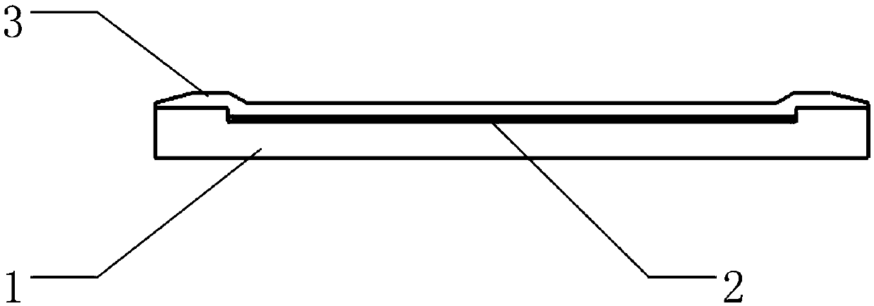
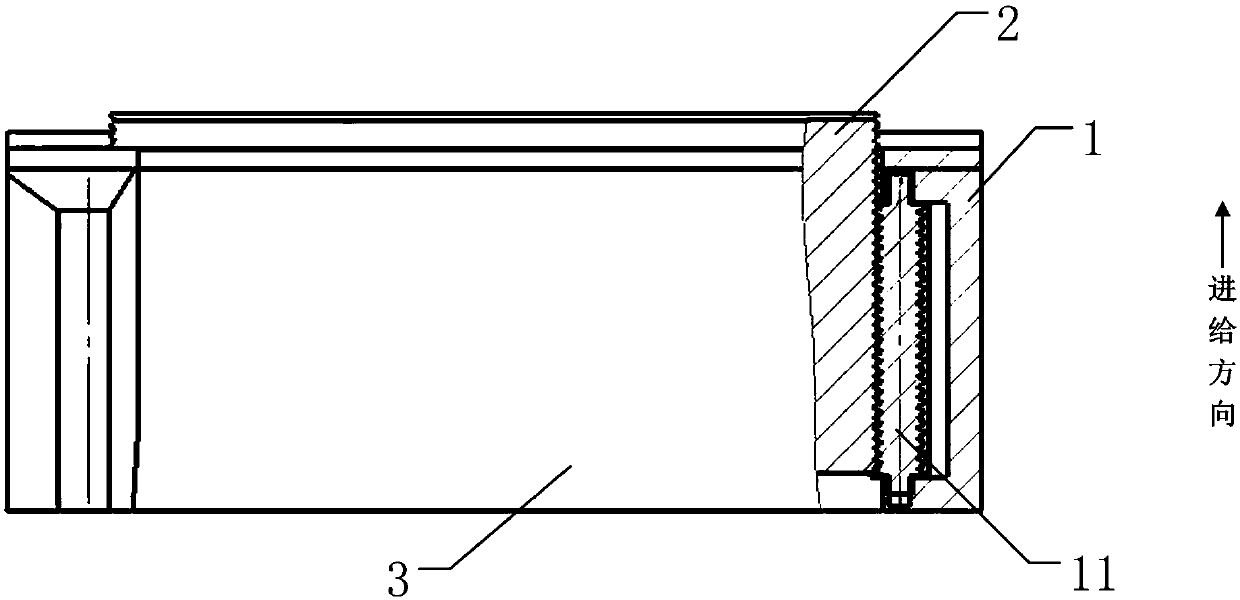
[0060] This example figure 2 As shown, the transmission part of the feeding device is a screw 11 , and the blade 2 is provided with a thread surface matching the thread of the screw 11 .

[0061] The blade has a certain thickness, so that the threaded surface can be formed on the side. The screw 11 is connected to the motor or connected to the drive through a transmission part. Helical movement, the blade 2 is provided with a thread surface matching the thread of the screw rod 11 on the feed side, when the screw rod 11 rotates, the raised thread can snap into the thread surface of the blade 2 feed side, and It can drive the blade 2 to move in the feeding direction.

[0062] The inclination direction of the thread is consistent with the inclination direction of the groove on the thread tooth surface to ensure that the screw 11 can drive the blade 2 to move. The specific parameters are set according to the design manual or actual needs. Those skilled in the art can achieve the...

Embodiment 3

[0065] The transmission components in this embodiment are lead screws and lead screw nuts, and protrusions are arranged on the blade 2 .

[0066] The screw and the screw nut can convert the rotational motion of the screw to the linear motion of the screw and nut along the screw through structures such as balls in the middle.

[0067] The lead screw nut is sleeved on the lead screw, and the linear motion is realized by the movement of the thread and the ball. The lead screw nut is provided with a nut protrusion, and the direction of the nut protrusion is the direction of the blade 2, and is aligned with the blade 2 for matching, the feeding side of the blade 2 is provided with a limit card slot matching with the nut protrusion, and a groove can be provided. When the screw rotates, it drives the screw nut to move back and forth. After the nut protrusion of the lead screw nut is snapped into the groove, the rotation of the screw rod drives the nut to move in the feeding direction...


PUM


Abstract

The invention discloses a tobacco cutter. The tobacco cutter comprises a cutter roller and a blade; a feeding device is arranged on the cutter roller; the blade has two feeding side edges parallel tothe feeding direction; a matched structure is arranged on at least one feeding side edge of the blade; the feeding device is in transmission fit with the matched structure of the blade so as to drivethe blade to move; or, the feeding device is in fixed fit with the blade, and synchronously moves with the blade; and thus, abrasion of the blade is compensated and/or the position of the blade in thefeeding direction is limited. The invention further discloses a control method of the tobacco cutter. The tobacco cutter and the control method thereof in the invention have the benefits that: afterbeing used out, the blade can be replaced without disassembling a clamping plate of the blade; therefore, the blade replacement time is greatly reduced; the downtime maintenance time is shortened; theclamping plate does not need to press the blade, so that the blade propulsion resistance is reduced; the space at the tail part of the blade is effectively saved; therefore, the length of the blade can be lengthened; the use time is prolonged; and the tobacco cutter can be suitable for cutter rollers, such as a hob type cutter roller and a rotary disc type cutter roller.

Description

technical field [0001] The invention belongs to the field of tobacco processing equipment, and in particular relates to a tobacco cutting machine and a control method thereof. Background technique [0002] The cutting machine is an important equipment in the tobacco shredding equipment and a main process equipment in the tobacco processing process. The uniformity and stability of the cut width play a very important role in the moisture balance and filling value of cut tobacco after drying. Because of its functional requirements, the wire cutter must keep the blade sharp, so the blade needs to be continuously ground, resulting in a continuous feeding and advancing mechanism for the blade. [0003] All kinds of shredding equipment at home and abroad mostly adopt the design structure with a pusher block at the bottom, and use a screw propulsion mechanism to push the blade at the bottom by the pusher block to realize feeding. At present, due to the influence of the design stru...

Claims


Application Information

Patent Timeline
Patent Type & Authority Applications(China)
IPC IPC(8): A24B7/04A24B7/14
CPCA24B7/04A24B7/14
Inventor 郭冬青王子亮陈磊苏玉龙姜志科郭中艳高星梅
Owner QINHUANGDAO TOBACCO MACHINERY
Why Eureka
Try Eureka