Turning control device for vehicle
A turning control and vehicle technology, applied in the direction of brakes, etc., can solve the problems of ineffectiveness, impracticality, reduction, etc., and achieve the effect of improving head turning and responsiveness
- Summary
- Abstract
- Description
- Claims
- Application Information
AI Technical Summary
Problems solved by technology
Method used
Image

Examples
Embodiment approach 1
[0053] First, refer to Figure 1 to Figure 9 The accompanying drawings illustrate Embodiment 1 of a turning control device for a vehicle according to the present invention.
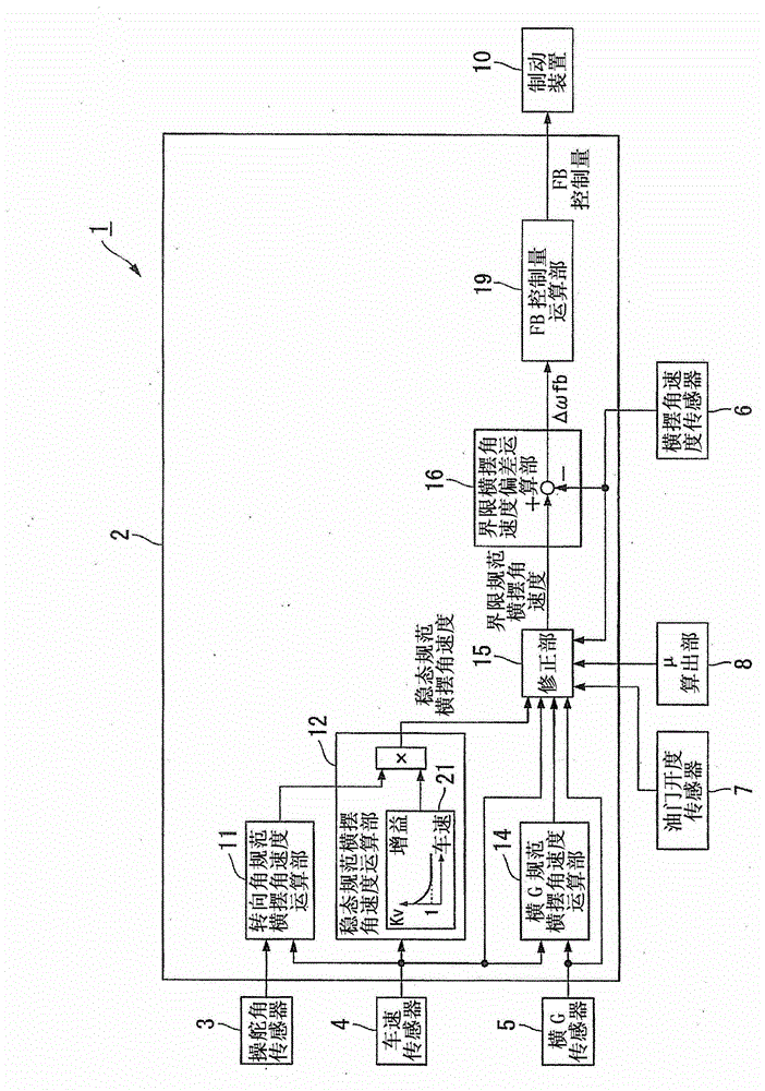
[0054] figure 1 It is a control block diagram of the vehicle turning control device according to the first embodiment.
[0055] A turning control device 1 for a vehicle includes a brake control unit 2 and a brake device 10 (brake control unit).
[0056] The brake control unit 2 determines braking force control amounts for the front, rear, left, and right wheels according to the running state of the vehicle. The brake device 10 controls the braking force of each wheel based on the braking force control amount of each wheel determined by the brake control unit 2 .
[0057] From the steering angle sensor 3 (steering amount detection unit) that detects the steering angle (steering amount) of the steering wheel of the vehicle, the vehicle speed sensor 4 (vehicle speed detection unit) that detects the vehicl...
Embodiment approach 2
[0133] Next, refer to Figure 10 and Figure 11 The accompanying drawings illustrate Embodiment 2 of the vehicle turning control device of the present invention.
[0134] Figure 10 It is a control block diagram of the vehicle turning control device according to the second embodiment. In the vehicle turning control device according to Embodiment 1 described above, the control amount (FB control amount) is obtained in the direction of eliminating the deviation between the limit standard yaw rate ω_TAR and the actual yaw rate (namely, the limit yaw rate deviation Δωfb). , only using the FB control amount to control the brake pressure. On the other hand, in the turning control device according to Embodiment 2, the feedforward control amount (hereinafter, simply referred to as FF control amount) is calculated based on the steering angle and the vehicle speed, and the FB control amount and the FF control amount are added together. The value is used as the total control amount, ...
Embodiment approach 3
[0166] Next, refer to Figure 12 to Figure 15 The accompanying drawings illustrate Embodiment 3 of the vehicle turning control device of the present invention.
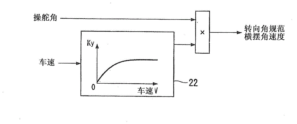
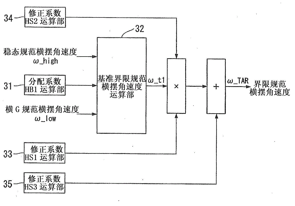
[0167] In Embodiment 1 above, the steady-state standard yaw rate ω_high is calculated by multiplying the steering angle standard yaw rate by the gain set according to the vehicle speed (steady-state standard yaw rate gain Kv), and the steady-state standard yaw rate The angular velocity ω_high is input to the correction unit 15 , and the lateral G standard yaw rate ω_low is corrected in association with the steady state standard yaw rate ω_high according to the steering state and motion state of the vehicle.
[0168] However, in vehicles, it is well known that there is a time delay in the yaw response relative to the steering input. However, no time delay is taken into account in the steering angle specification yaw rate. Therefore, in the third embodiment, the steering angle standard yaw rate taking the time delay i...
PUM
 Abstract
Description
Claims
Application Information
 - R&D
- Intellectual Property
- Life Sciences
- Materials
- Tech Scout
- Unparalleled Data Quality
- Higher Quality Content
- 60% Fewer Hallucinations
Browse by: Latest US Patents, China's latest patents, Technical Efficacy Thesaurus, Application Domain, Technology Topic, Popular Technical Reports.
© 2025 PatSnap. All rights reserved.Legal|Privacy policy|Modern Slavery Act Transparency Statement|Sitemap|About US| Contact US: help@patsnap.com