Precise solar energy glass laser scribing method

A solar glass, laser scribing technology, applied in laser welding equipment, electrical components, climate sustainability, etc., can solve the problem of low parallelism yield between lines, and achieve the effect of improving parallelism

Inactive Publication Date: 2012-10-31
HORNG TERNG AUTOMATION
View PDF7 Cites 5 Cited by
  • Summary
  • Abstract
  • Description
  • Claims
  • Application Information

AI Technical Summary

Problems solved by technology

[0008] In view of the problems existing in the above-mentioned prior art, the present invention provides a high-precision solar glass laser scribing method, hoping to design and solve the prior art laser scribin

Method used


Image

  • Precise solar energy glass laser scribing method
  • Precise solar energy glass laser scribing method
  • Precise solar energy glass laser scribing method

Examples


Embodiment Construction

[0023] The technical means adopted by the present invention to achieve the intended invention purpose are further described below in conjunction with the drawings and preferred embodiments of the present invention.

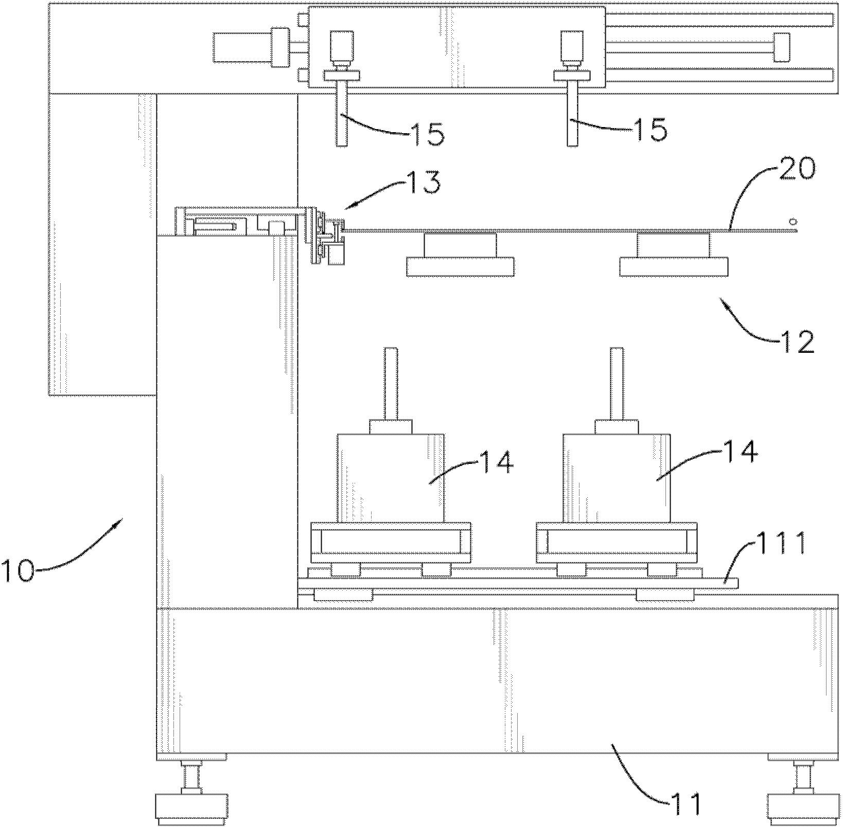
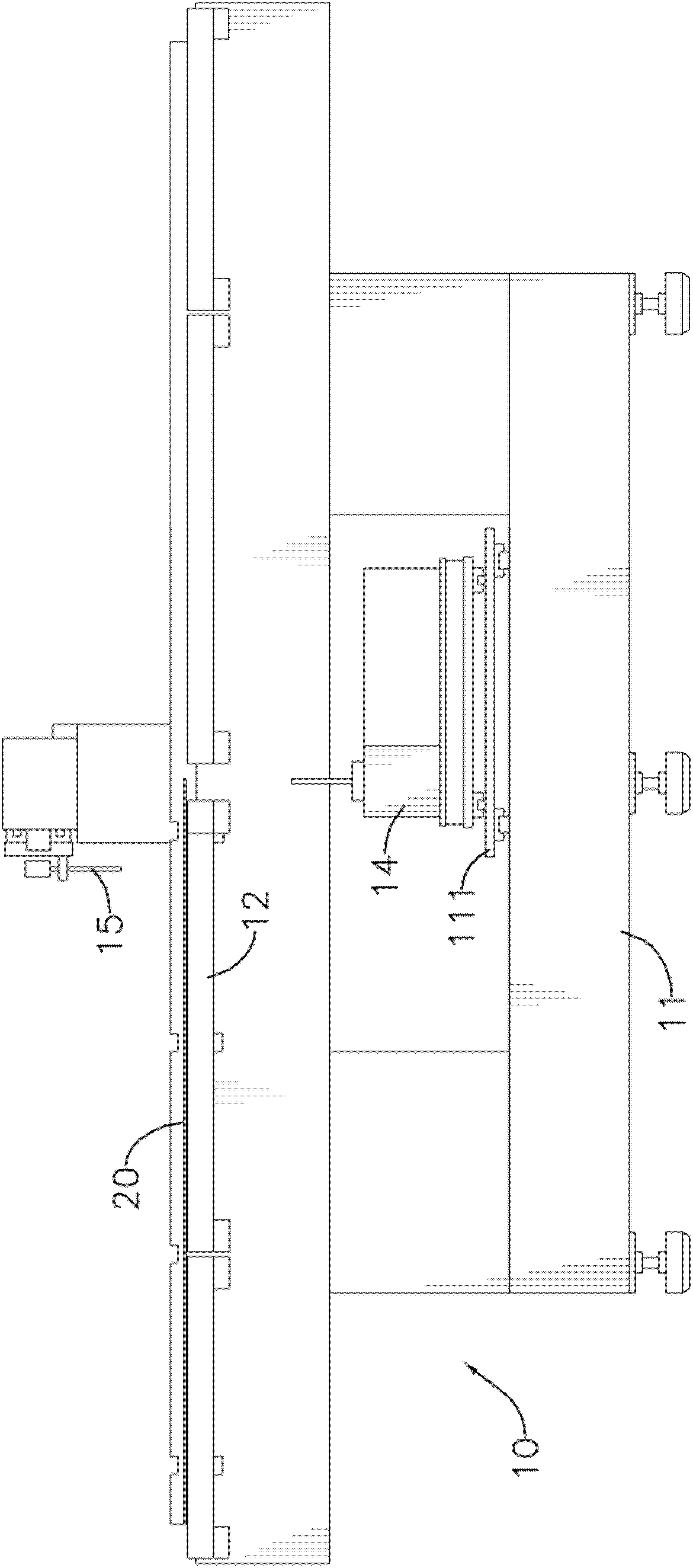
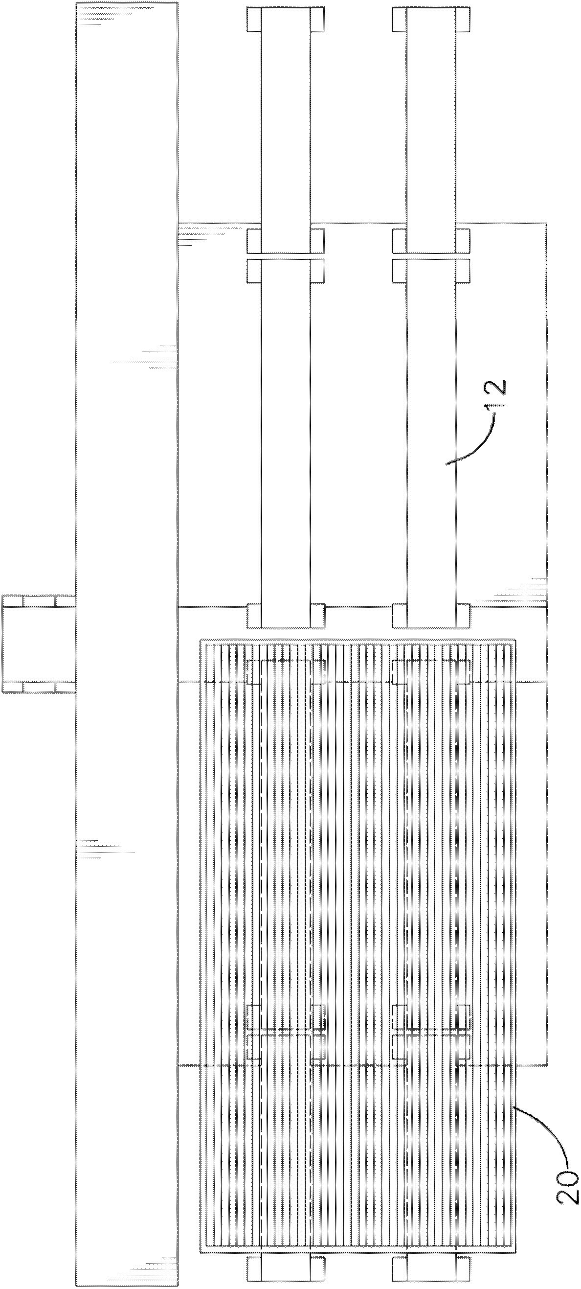
[0024] see Figure 1 to Figure 3 As shown, the high-precision solar glass laser scribing method of the present invention is achieved by using a laser scribing device 10. The laser scribing device 10 includes a machine 11, an air-floating platform 12, a clamping mechanism 13, at least A laser scribing device 14 and at least one visual alignment device 15: a mobile platform 111 is provided on the machine platform 11, and the mobile platform 111 can move back and forth in one direction on the machine platform 11; the air floating platform 12 is erected on Above the machine 11, a substrate 20 to be processed by laser scribing is located above the air flotation platform 12, and the substrate 20 is supported by the gas generated by the air flotation platform 12, so that...


PUM


Abstract

Disclosed is a precise solar energy glass laser scribing method, comprising a straight line image-taking action and a laser scribing action, The straight line image-taking action respectively takes images of two straight lines scribed in the film layer of previous manufacturing process upon the substrate, thus to obtain two-point coordinate of each straight line and master the line slope of each straight line as well as the distance between lines. Then, the laser scribing action carries out image taking over the film layer of the following manufacturing process upon the substrate, and timely adjusts the line slope of the straight line scribed by the laser scribing apparatus in the following manufacturing process, thereby realizing the objective of raising the depth of parallelism between every two straight lines.

Description

technical field [0001] The invention relates to a high-precision solar glass laser scribing method that can effectively improve the parallelism between scribed lines. Background technique [0002] One of the manufacturing methods of silicon thin-film solar cells is to first generate a transparent conductive film layer (Transparent Conducting Oxide, TCO) on a substrate, and use a laser to draw spaced straight lines on the transparent conductive film layer, so that Separate the transparent conductive film layer into several isolated areas; then lay an amorphous silicon film layer on the transparent conductive film layer by sputtering or plasma-enhanced chemical vapor deposition (Plasma-Enhanced Chemical Vapor Deposition, PECVD) , and also use the laser to draw a straight line on the amorphous silicon thin film layer; then lay a metal thin film layer on the amorphous silicon thin film layer, and also use the laser to draw a straight line on the metal thin film layer. [0003] ...

Claims


Application Information

Patent Timeline
IPC IPC(8): B23K26/36B23K26/03B23K26/02H01L31/18B23K26/362
CPCY02P70/50
Inventor 王裕贤张振昌简瑞胤
Owner HORNG TERNG AUTOMATION
Why Eureka
Try Eureka