
Air-jet loom

An air-jet loom and air pump technology, which is applied in looms, textiles, textiles and papermaking, etc., can solve the problems of narrow weft density range of woven fabrics, and achieve the effect of less equipment investment and compact structure

Active Publication Date: 2012-10-31
QINGDAO KAISHUO MACHINERY TECH CO LTD
View PDF6 Cites 4 Cited by
  • Summary
  • Abstract
  • Description
  • Claims
  • Application Information

AI Technical Summary

Problems solved by technology

In production practice, it is found that the above-mentioned beat-up angle formed by the above-mentioned beat-up foot is suitable for a narrow range of weft density in weaving fabrics, which has considerable limitations.

Method used


Image

  • Air-jet loom
  • Air-jet loom
  • Air-jet loom

Examples


Embodiment Construction

[0020] An air-jet loom comprises a shedding mechanism, an airflow weft insertion mechanism, a weft beating mechanism, a let-off mechanism, a coiling mechanism and other auxiliary mechanisms. Except for the following differences, other relevant components can be realized by adopting or referring to existing technologies.

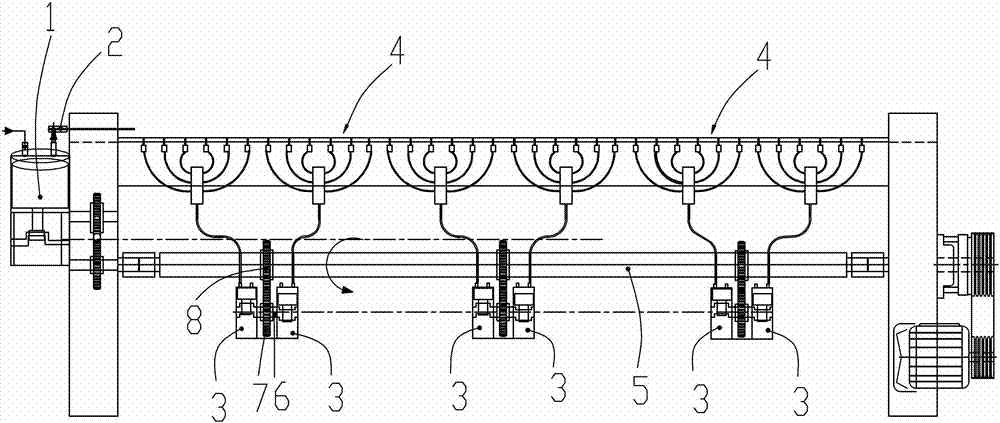
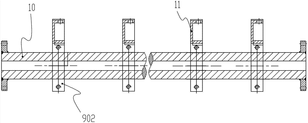
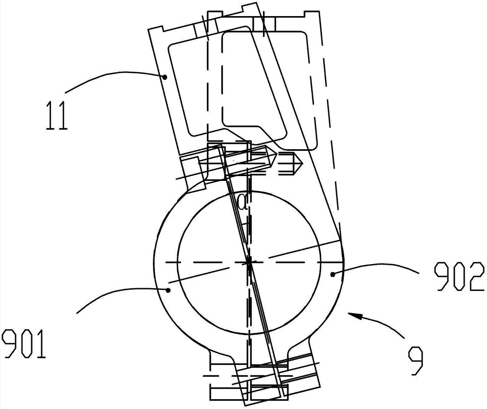
[0021] combine figure 1 , the above-mentioned airflow weft insertion mechanism includes a main air pump 1, a main nozzle 2, several auxiliary air pumps 3, an auxiliary nozzle group 4 having the same number as the auxiliary air pumps, and an air pump drive shaft 5; the above-mentioned main air pump is a plunger type air pump, and each auxiliary air pump Also all are plunger type air pumps, this example selects six auxiliary air pumps and six groups of auxiliary nozzle groups. The above-mentioned main nozzles are connected to the main air pump, and each auxiliary nozzle group is respectively connected to an auxiliary air pump, the main nozzle is fixed on the s...


PUM


Abstract

The invention discloses an air-jet loom. The air-jet loom comprises an opening mechanism, an air flow weft introducing mechanism, and a battening mechanism, and is characterized in that the air flow weft introducing mechanism comprises a main air pump, a main nozzle, a plurality of assistant air pumps, assistant nozzle sets, and air pump transmission shafts, wherein each of the air pumps is plunger type air pump; the main nozzle is connected with the main air pump; each of the assistant nozzle sets is connected to one of the assistant air pumps, respectively; the main nozzle is fixed to a weft throwing starting point; the assistant nozzle sets are sequentially fixed to the weft throwing path; a piston rod of the main air pump is connected with the air pump transmission through a transmission subassembly; the piston rods of the assistant air pumps are connected with the air pump transmission shafts through related transmission subassemblies; all the assistant air pumps are arranged in a line along the air pump transmission shafts; and the weft is thrown between one of the assistant nozzle sets at the downstream of the weft throwing path and one of the assistant nozzle sets at the adjacent upstream in a relay way through the jetting air flow. The air-jet loom is dispensed with sharing of a main pump station of the prior art; and the air-jet loom has the characteristics of low investment on equipment, compactness in structure, energy conservation performance, and consumption reducing performance, etc.

Description

technical field [0001] The present invention relates to an air jet loom. Background technique [0002] The technical structure of the air-jet loom in the prior art mainly includes parts such as shedding mechanism, air-flow weft insertion mechanism, beating-up mechanism, warp let-off mechanism, coiling mechanism and other auxiliary mechanisms. Its main working principle is roughly: the shedding mechanism drives the heald frame to move up and down, so that the warp yarns form a shed, and the airflow weft insertion mechanism brings the weft yarns into the shed through the airflow, and then the reed is driven by the beating mechanism to enter the shed. The weft yarn is driven into the fell to weave into cloth. The above-mentioned air flow weft insertion mechanism includes a main nozzle, which is fixed at the starting point of weft yarn projection through a multi-purpose seat, and the main nozzle is connected to the main pumping station in the weaving site through an air supply ...

Claims


Application Information

Patent Timeline
Patent Type & Authority Applications(China)
IPC IPC(8): D03D47/30D03D49/60
Inventor 邢桂松
Owner QINGDAO KAISHUO MACHINERY TECH CO LTD
Learn More