LED (light-emitting diode) flooding total-reflection lens and LED lamp using same

A technology of LED light source and total reflection, which is applied in the field of lenses, can solve the problems of high light intensity, small floodlight angle, and strong light, and achieve the effects of high light efficiency utilization, high uniformity of illumination, and small size

Active Publication Date: 2012-10-31
OCEANS KING LIGHTING SCI&TECH CO LTD +1
View PDF3 Cites 2 Cited by
  • Summary
  • Abstract
  • Description
  • Claims
  • Application Information

AI Technical Summary

Problems solved by technology

[0002] The floodlight method of LEDs generally adopts reflective cup light distribution, but this method is not very ideal for the treatment of light. Although light distribution can be made through the reflector, the light distribution through the reflector will make the reflective cup along the direction of the LED optical axis The intensity of light is greater, that is, the intensity of light in the middle part is higher
[0003] There is also a convex lens to condense the LED light, but this method has a relatively low utilization rate of the LED luminous flux, which means that the light with a large luminous angle of the LED cannot be used, which eventually leads to a low light efficiency utilization rate of the lamp.
[0004] At present, there is also a class of flood mirrors, which are used in LED condenser total reflection mirrors (such as figure 1 Shown), on the basis of its exit surface ( figure 1 In 100), the densely distributed small bumps (or concave holes) are processed to achieve the floodlight effect, and there are also methods of frosting the exit surface. The floodlight effect achieved by these treatment methods is not uniform enough, and the floodlight angle is general Smaller, less efficient use of light
[0005] In addition, the side rotation generatrix of existing reflectors is generally a straight line or a parabola, so the size of the lens that meets the light distribution is relatively large

Method used


Image

  • LED (light-emitting diode) flooding total-reflection lens and LED lamp using same
  • LED (light-emitting diode) flooding total-reflection lens and LED lamp using same
  • LED (light-emitting diode) flooding total-reflection lens and LED lamp using same

Examples


Embodiment Construction

[0036] The preferred embodiments of the present invention will be described in detail below in conjunction with the drawings.

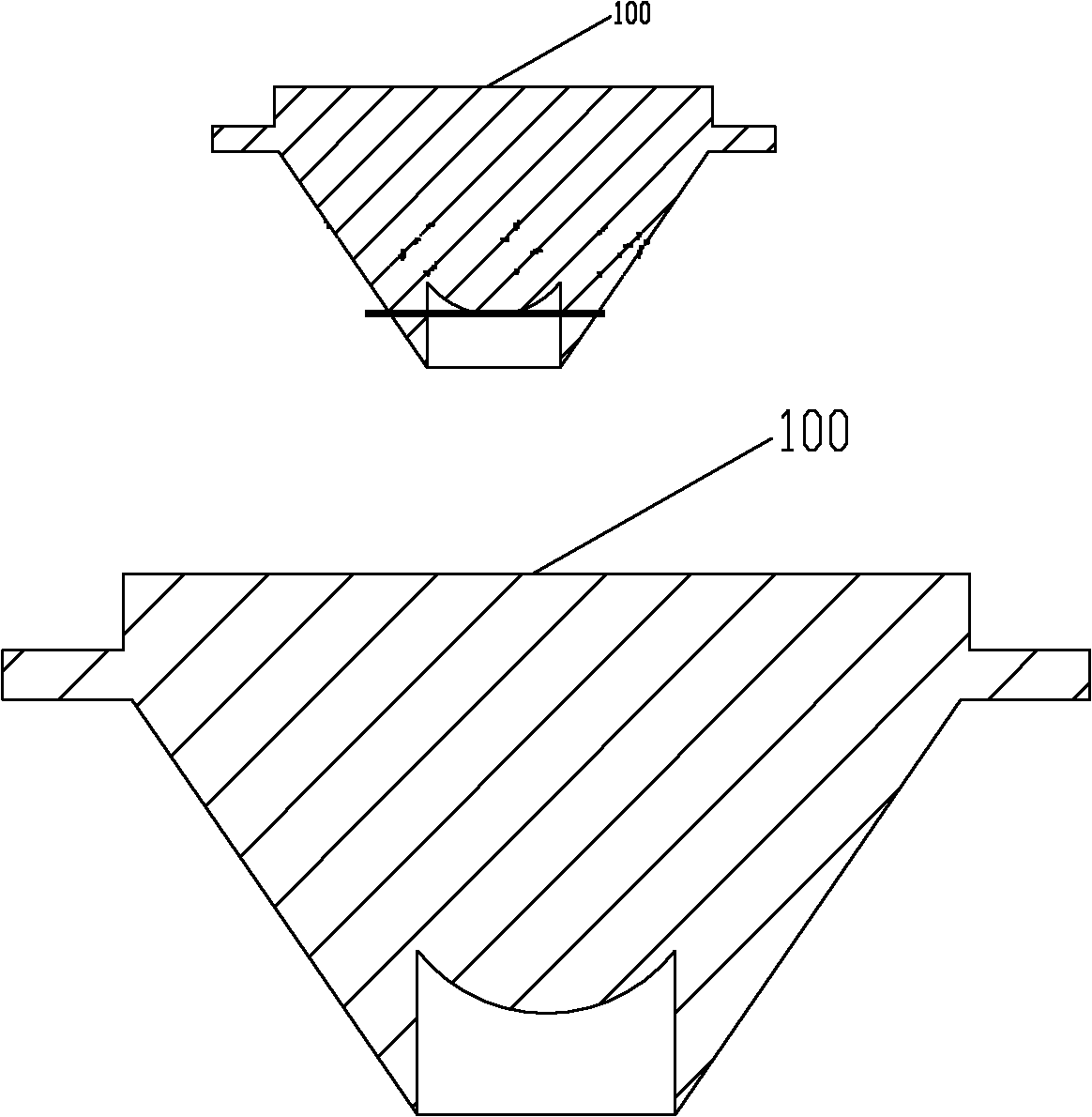
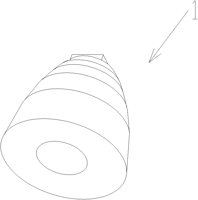
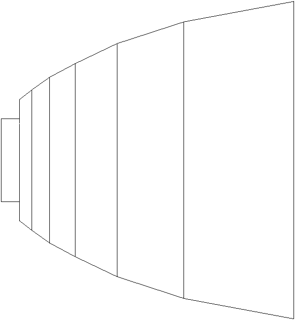
[0037] like figure 2 shown, see also image 3 , Figure 4 and Figure 5 . The total reflection lens 1 is a body of revolution, which is formed by turning a folded line around the optical axis of the total reflection lens 1 . The light incident surface of the total reflection lens 1 is provided with a blind hole 2 for installing an LED light source, and the axis of the blind hole 2 coincides with the optical axis of the total reflection lens 1 . The LED light source is placed in the blind hole 2 so that its light-emitting chip falls on the light incident surface of the total reflection lens 1 and its optical axis coincides with the optical axis of the total reflection lens 1 . In addition, the light emitting surface of the total reflection lens 1 is further provided with a concave spherical surface, and the center of the concave spherical surface...


PUM


Abstract

The invention relates to an LED (light-emitting diode) flooding total-reflection lens and an LED lamp using the same. The total-reflection lens is characterized in that the total-reflection lens is a solid of revolution; the solid of revolution is formed in such a manner that a broken line revolves around the optical axis of the total-reflection lens; a blind hole for installing an LED light source is formed on the incidence surface of the total-reflection lens; the axis of the blind hole coincides with the optical axis of the total-reflection lens; the LED light source is arranged in the blind hole; the light-emitting chip of the LED light source falls on the incidence surface of the total-reflection lens and the optical axis of the light-emitting chip coincides with that of the total-reflection lens; a concave sphere is also arranged on the emergence surface of the total-reflection lens; and the sphere center of the concave sphere falls on the optical axis. The total-reflection lens has the following beneficial effects that the total-reflection lens adopts the broken line as a revolving generatrix, so that the size of the LED lamp can be small as much as possible and the lighting effect utilization rate is high on the premise that the LED lamp meets the illuminance requirement; and the angle of the LED light near the optical axis can be expanded via the concave sphere on the emergence surface, thus partial light can not be excessively centralized and the LED lamp has high uniformity of illuminance in the irradiated region with the light-emitting angle being 20 degrees.

Description

technical field [0001] The invention relates to a lens, and more specifically relates to a lens suitable for LEDs with a flood light distribution function and a lamp using the lens. Background technique [0002] The floodlight method of LEDs generally adopts reflective cup light distribution, but this method is not very ideal for the treatment of light. Although light distribution can be made through the reflector, the light distribution through the reflector will make the reflective cup along the direction of the LED optical axis The light intensity of is larger, that is, the light intensity of the middle part is higher. [0003] Convex lenses are also used to condense LED light, but this method has a relatively low utilization rate of LED luminous flux, which means that the light with a large LED luminous angle cannot be used, which eventually leads to low light efficiency utilization of the lamp. [0004] At present, there is also a class of flood mirrors, which are used...

Claims


Application Information

Patent Timeline
Patent Type & Authority Applications(China)
IPC IPC(8): F21V5/04F21Y101/02
Inventor 周明杰罗英达
Owner OCEANS KING LIGHTING SCI&TECH CO LTD
Why Eureka
Try Eureka