
Liquid crystal lens

A technology of a liquid crystal lens and a liquid crystal layer, which is applied in the directions of lenses, optics, instruments, etc., can solve the problems of complex design of the liquid crystal lens structure 200, etc.

Inactive Publication Date: 2012-10-31
SILICON TOUCH TECH INC
View PDF4 Cites 8 Cited by
  • Summary
  • Abstract
  • Description
  • Claims
  • Application Information

AI Technical Summary

Problems solved by technology

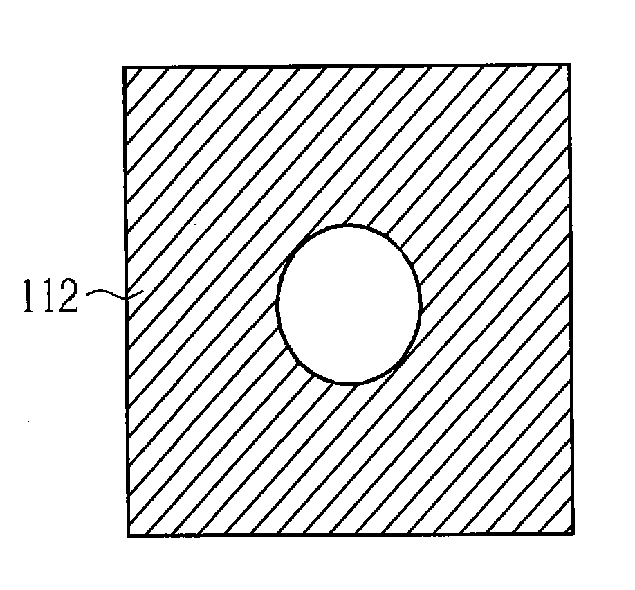
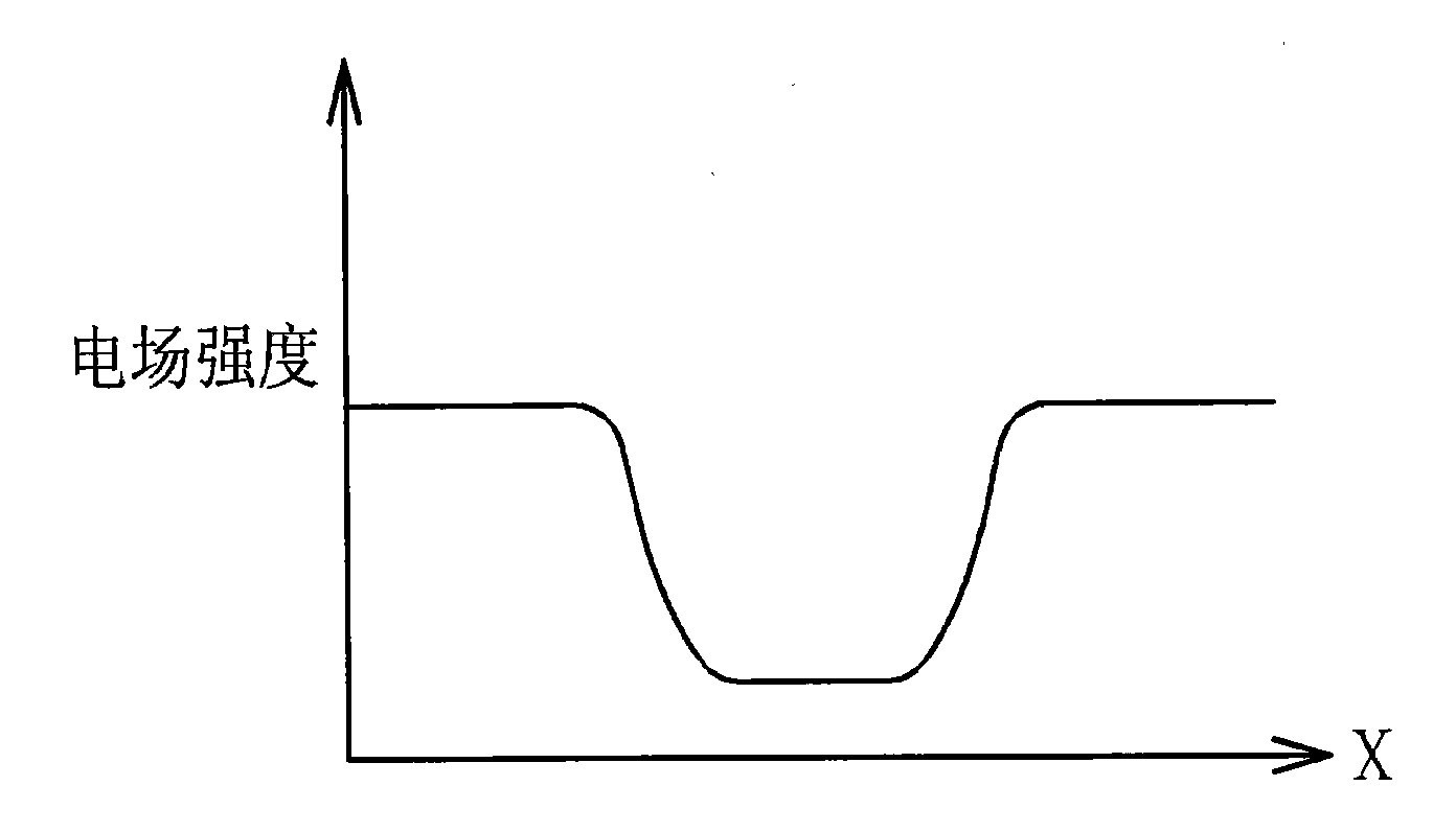
Although as Figure 2C The shape of the electric field intensity distribution inside the liquid crystal layer 230 shown is compared to Figure 1C The distribution shape of the electric field intensity in the liquid crystal layer 130 shown is good, but because multiple control voltages V1-V3 are required, the design of the liquid crystal lens structure 200 will be relatively complicated.

Method used


Image

  • Liquid crystal lens
  • Liquid crystal lens
  • Liquid crystal lens

Examples


Embodiment Construction

[0031] Please refer to Figure 3A , Figure 3A It is a schematic diagram of a liquid crystal lens 300 according to an embodiment of the present invention. Such as Figure 3A As shown, the liquid crystal lens 300 includes two glass layers 310 and 320 , two ITO electrode layers 312 and 322 respectively formed on the two glass layers 310 and 320 , and a liquid crystal layer 330 . Figure 3B Shown is a top view of the ITO electrode layer 312, wherein the ITO electrode layer 312 has a plurality of concentric ring electrodes (in this embodiment, three concentric ring electrodes 312_1-312_3), and adjacent The distance between two concentric circular electrodes decreases along the outward radial direction, wherein the word "distance" refers to the minimum distance between two adjacent concentric circular electrodes. In addition, the connecting electrodes 350 are used to connect the concentric circular electrodes 312_1 - 312_3 , and the concentric circular electrodes 312_1 - 312_3 a...


PUM


Abstract

A liquid crystal lens includes a first light-pervious plate, a second light-pervious plate, a first electrode layer arranged on the first light-pervious plate, a second electrode layer arranged on the second light-pervious plate, and a liquid crystal layer sandwiched between the first light-pervious plate and the second light-pervious plate, where the first electrode layer comprises a plurality of concentric electrodes, and a gap between two adjacent outer concentric electrodes is different from a gap between two adjacent inner concentric electrodes.

Description

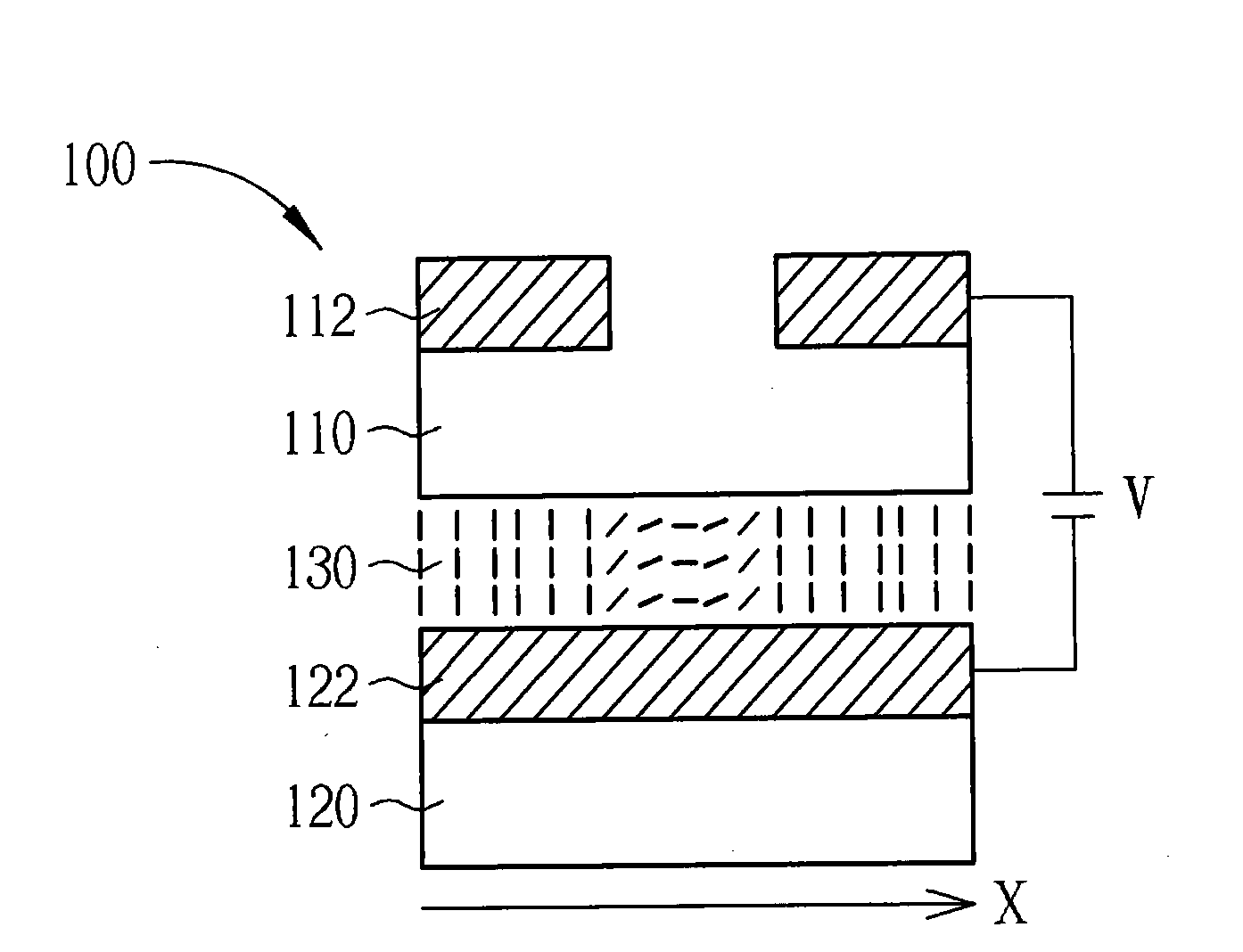
technical field [0001] The present invention relates to liquid crystal lenses. Background technique [0002] Liquid crystal lens (liquid crystal lens) is a technology created by utilizing the unique physical and optical properties of liquid crystal materials. Unlike traditional glass lenses, liquid crystal lenses can focus or diverge incident light according to the electric field applied to them. In particular, the focal length of liquid crystal lenses can be adjusted by changing the supply voltage. Because liquid crystal lenses do not require the use of mechanical action to adjust focus, liquid crystal lenses are more suitable than traditional glass lenses for many image acquisition techniques. [0003] Please refer to Figure 1A , Figure 1A is a schematic diagram of a known liquid crystal lens structure 100 . The liquid crystal lens structure 100 includes two glass layers 110 and 120 , two Indium-Tin Oxide (ITO) electrode layers 112 and 122 respectively formed on the tw...

Claims


Application Information

Patent Timeline
IPC IPC(8): G02F1/29G02F1/1343
CPCG02F2203/22G02F2203/28G02F2001/134318G02F1/134309G02F2001/294G02B3/14G02F1/134318G02F1/294
Inventor 毕少强
Owner SILICON TOUCH TECH INC
Learn More