Heat exchanger

A technology for heat exchangers and heat exchangers, which is applied to heat exchanger fixing, heat exchange equipment, heat exchangers, etc., can solve the problems of increased thickness, inability to implement stamping process, etc., and achieve the effect of increasing compactness

Active Publication Date: 2012-10-31
VALEO SYST THERMIQUES
View PDF6 Cites 20 Cited by
  • Summary
  • Abstract
  • Description
  • Claims
  • Application Information

AI Technical Summary

Problems solved by technology

So, faced with a dilemma, if the thickness of the header plate is increased (by makin

Method used


Image

  • Heat exchanger
  • Heat exchanger
  • Heat exchanger

Examples


Embodiment Construction

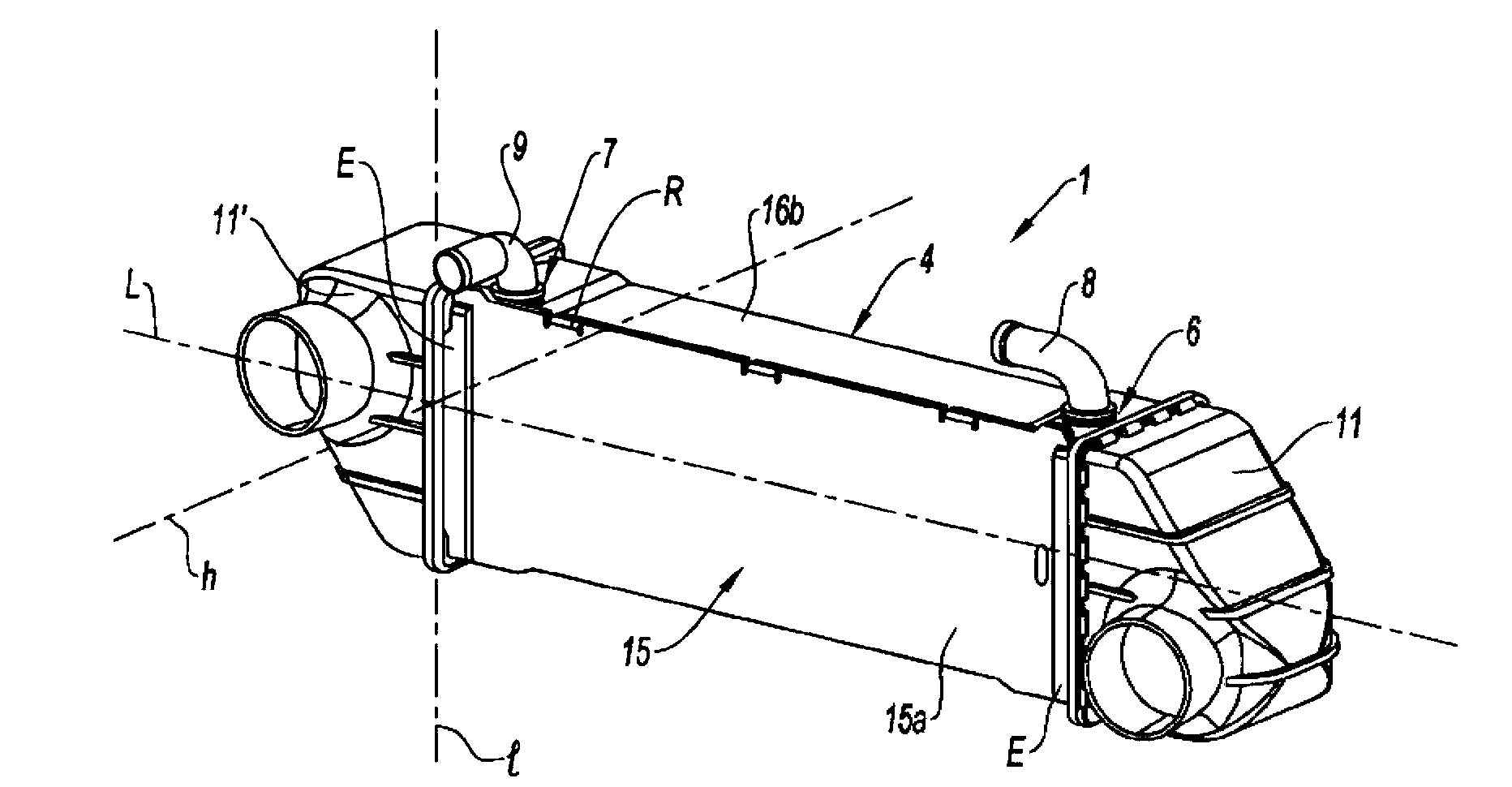
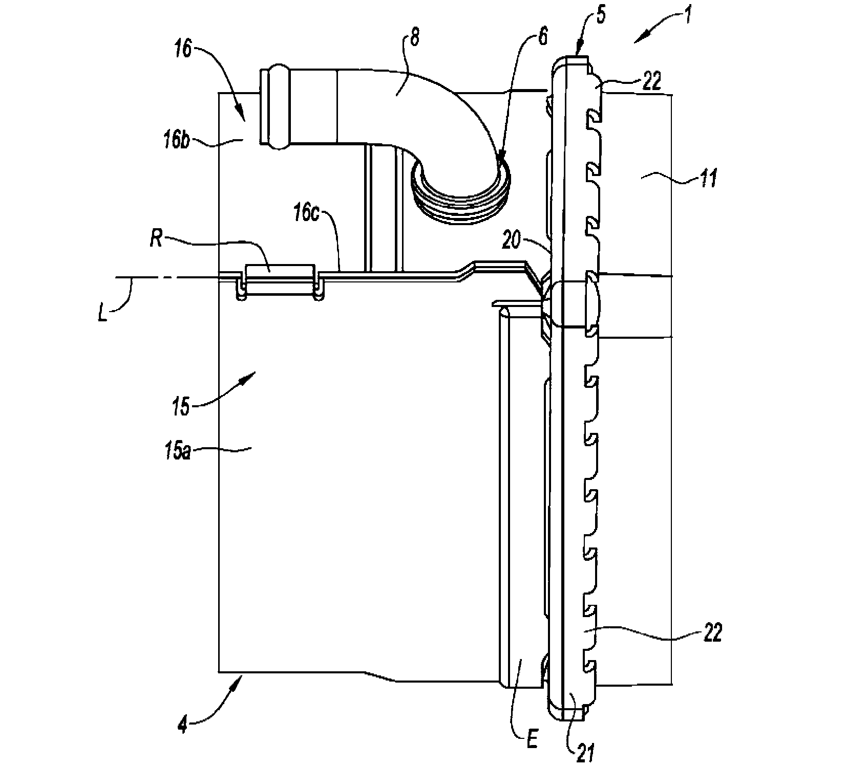
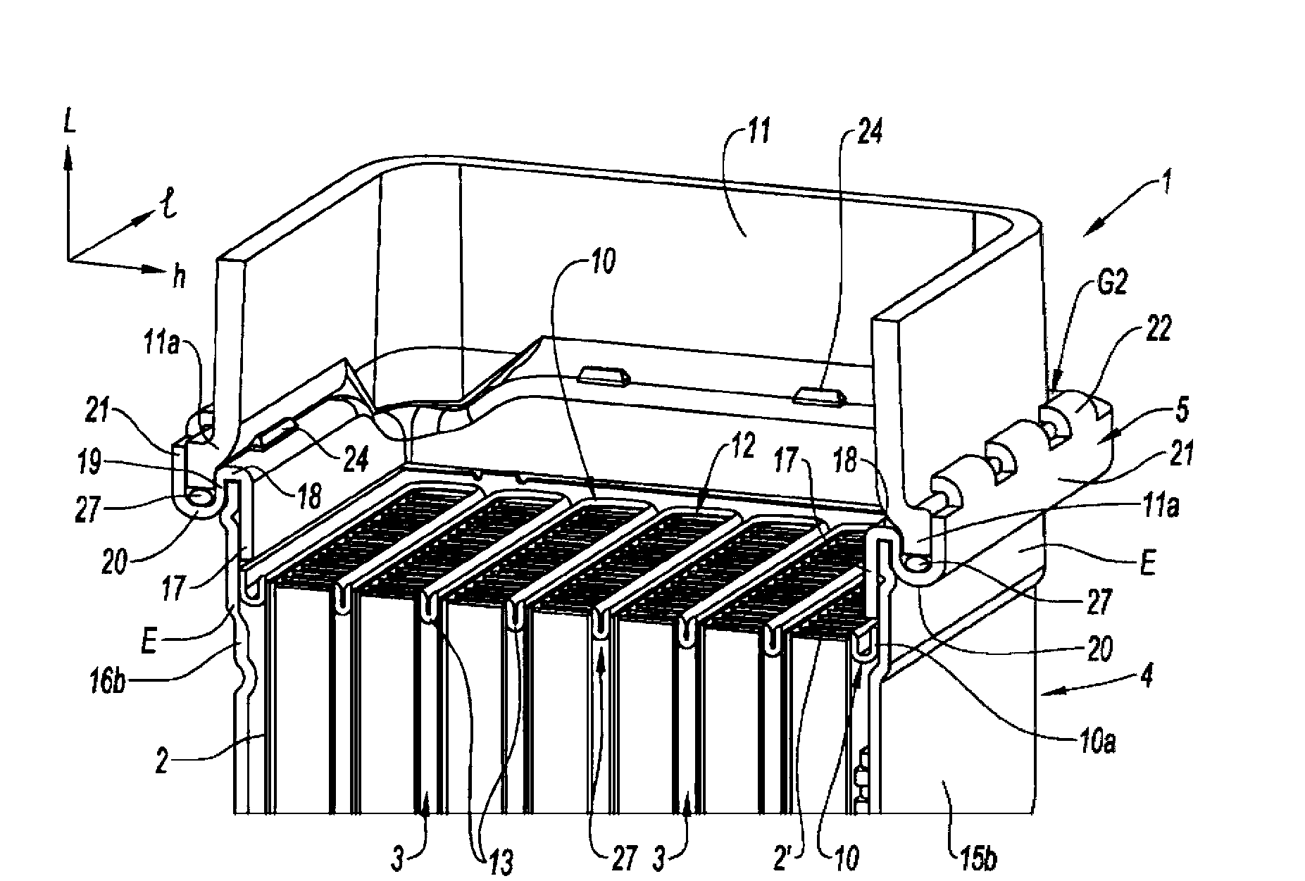
[0043] With reference to the accompanying drawings, and more particularly to Figures 1 to 6, the heat exchanger 1 according to the first embodiment comprises heat exchanging components 2, 2', 3, a housing 4 for receiving or accommodating said components 2, 2', 3, an air inlet collecting box 11 and an air outlet Collection box 11'. The housing 4 comprises openings 6, 7 for connection to pipes 8, 9 for the flow of water, in this particular case an inlet pipe 9 and an outlet pipe 8, said pipes being connected to the water circuit where the exchanger 1 is installed in the water circuit. In the described embodiment, the different parts of the exchanger 1 are brazed to each other, except for the crimped boxes 11, 11'; such exchangers with brazed or crimped exchanger parts are by their usual nature are well known to those skilled in the art.

[0044] Exchanger 1 describes a so-called "air-water" exchanger, ie an exchanger in which the heat-exchanging fluids are air and water. Fo...


PUM


Abstract

The invention relates to a heat exchanger comprising fluid exchange and flow elements (2, 2', 3), at least one fluid-collecting box (11, 11') into which the exchange elements (2, 2', 3) lead, at least one collecting plate (10) holding the exchange elements (2, 2', 3) and a casing (4) for housing the exchange elements (2, 2', 3). The exchanger is characterized in that it comprises a flange (5) for attaching the collecting box (11, 11') to the casing (4). Owing to the invention, stresses are prevented from being transmitted from the flange (5) to the collecting plate (10), thereby enabling a thinner collecting plate (10) to be produced.

Description

technical field [0001] The present invention relates to heat exchangers. Background technique [0002] Heat exchangers, such as are used in the automotive industry and more precisely in thermal internal combustion engines of motor vehicles, comprising heat exchange parts and fluid flow parts in which fluid circulates, between them heat exchange between them. Heat exchange components may include, for example, tubes, plates, fins, flow agitators, and the like. Many structural configurations are conceivable. For example, an exchanger may comprise a core of tubes arranged in parallel with respect to each other in one or more rows, the rows also being parallel, the tubes being designed to transport a first fluid while the second fluid is flows between them and exchanges heat with the first fluid. Many fluid associations are conceivable, whether they are liquids and / or gases. [0003] The exchanger comprises a housing for receiving the tubing, the housing including a pluralit...

Claims


Application Information

Patent Timeline
IPC IPC(8): F28D7/16F28F9/02
CPCF28F9/0219F28D21/0003F28D1/0233F28D1/05333F28D7/1684F28F9/0226F28F2275/122
Inventor P.加雷特E.皮尼亚斯基
Owner VALEO SYST THERMIQUES
Why Eureka
Try Eureka