Tension self-locking device for grouting anchor cable

A self-locking device and pulling force technology, applied in the installation of bolts, mining equipment, earthwork drilling, etc., can solve the problems of lower utilization rate of anchoring agent, lower anchoring efficiency, and failure to reach the expected pullout resistance of anchor cables. Simple installation, increase anchoring efficiency, and avoid the effect of looseness in the hole

Inactive Publication Date: 2012-11-07
ANHUI JINXING PRESTRESSING ENG TECHCO
View PDF5 Cites 6 Cited by
  • Summary
  • Abstract
  • Description
  • Claims
  • Application Information

AI Technical Summary

Problems solved by technology

In recent years, the roadway support tools commonly used in coal mines are ordinary prestressed anchor cables. Although the anchor cable has a strong bearing capacity, the anchoring end uses an anchoring agent to solidify the steel strand and the internal rock. The theoretical pullout resistance of the anchor cable can reach 318KN (with Φ22 anchor cable as an example), but due to the complex underground geological environment and different geotechnical structures, the anchor cable cannot be completely installed in the hole or the angle is generated when it is installed. In addition, the plastic packaging used for packaging the anchoring agent is The hole cannot be cleaned, and a diaphragm is easily formed between the anchor cable and the anchoring agent, which greatly reduces the utilization rate of the anchoring agent, fails to reach the expected pullout resistance of the anchor cable, and greatly reduces the anchoring efficiency, so that the safety of the coal mine cannot be guaranteed

Method used


Image

  • Tension self-locking device for grouting anchor cable
  • Tension self-locking device for grouting anchor cable

Examples


Embodiment Construction

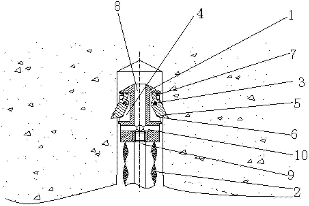
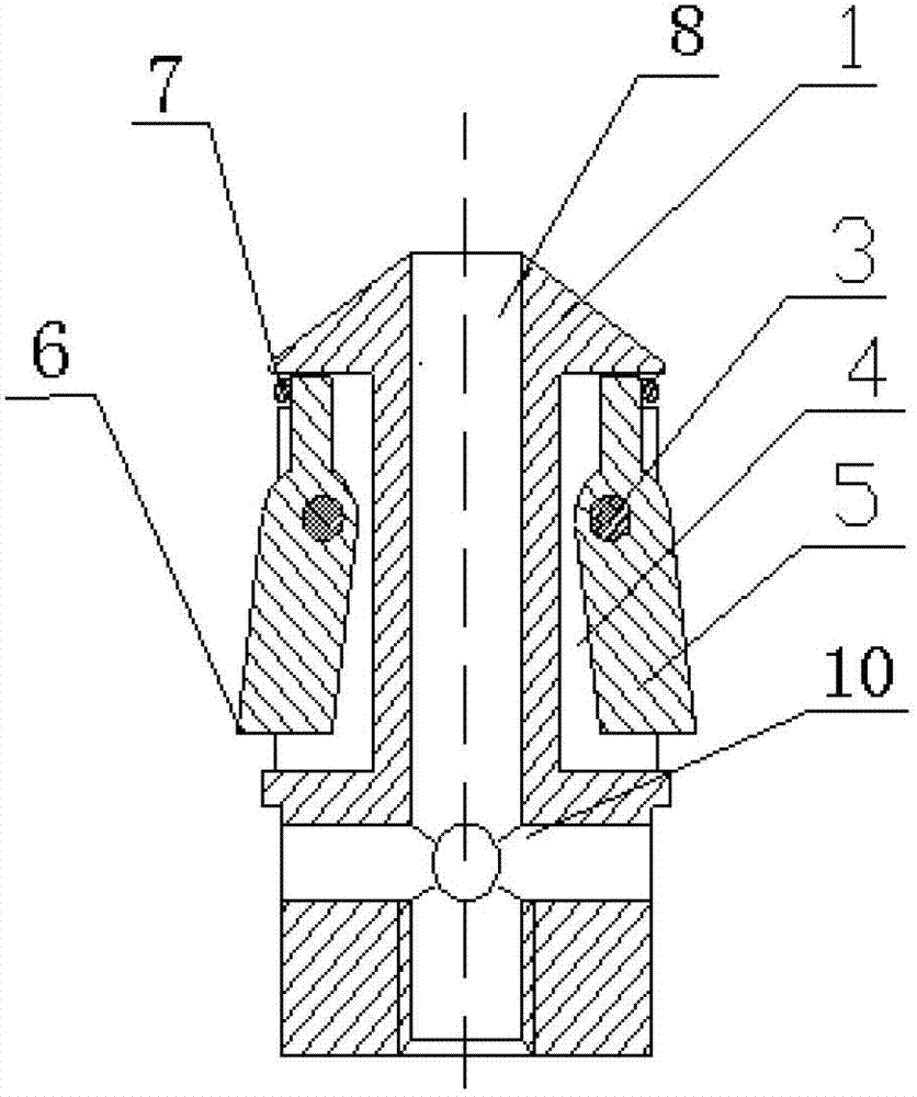
[0015] Referring to the accompanying drawings, a tension self-locking device for grouting anchor cables includes a lock claw seat 1 fixedly connected to the front end of the cable body 2, and the cable body 2 extends into the lock claw seat 1 through a central grouting pipe. The front end of the lock claw seat 1 is sharpened, and the side wall of the lock claw seat 1 is provided with a ring groove 4, and in the ring groove 4, 6 pieces of single-piece lock claws 5 distributed in the circumferential direction are hinged through the revolving pin 3, and the single-piece lock claw 5 The bottom end is tilted outward, and the bottom end of the single-piece lock claw 5 has lock teeth 6 that can be embedded in the inner wall of the tunnel. Grouting channel 8, the central grouting channel 8 communicates with the front end of the central grouting pipe 9, the front end of the central grouting pipe 9 is threadedly connected to the bottom end of the locking claw seat 1, and the outer side o...


PUM


Abstract

The invention discloses a tension self-locking device for a grouting anchor cable. The device comprises a locking jaw seat fixedly connected to the front end of a cable body. A central grouting pipe penetrates through the cable body, and is extended into the locking jaw seat. The front end of the locking jaw seat is sharpened. A ring groove is reserved on the sidewall of the locking jaw seat. 4 to 16 annularly distributed single-piece locking jaws are hinged in the ring groove. The bottom ends of the single-piece locking jaws are outwards tilted. Locking teeth are arranged at the bottom ends of the single-piece locking jaws, and can be embedded into the inner wall of pore passages. Spring rings are sleeved at the front ends of the annularly distributed single-piece locking jaws. A central grouting pore passage is reserved in the locking jaw seat, and is communicated with the front end of the central grouting pipe. A communicated radial grouting pore passage is reserved outside the central grouting pore passage. The single-piece locking jaws and pore walls keep a good contact state, and the locking teeth are arranged at the bottom ends of the single-piece locking jaws, and can be embedded into the inner walls of the pore passages, so that the single-piece locking jaws can be flexibly embedded into the inner walls of the pore passages when the whole anchor cable is tensioned, and can be reversely stressed and self-locked, and smooth grouting is ensured.

Description

technical field [0001] The invention relates to a tension self-locking device for grouting anchor cables. Background technique [0002] Underground coal mine roadway support is a very important link in the production process. It is related to the safety of workers in underground operations. It is also an important factor for coal mines to produce more coal, increase production, and reduce roadway maintenance workload and costs. In recent years, the roadway support tool commonly used in coal mines is the ordinary prestressed anchor cable. Although the anchor cable has a strong bearing capacity, the anchoring end uses an anchoring agent to solidify the steel strand and the internal rock. The theoretical pullout resistance of the anchor cable can reach 318KN (with Φ22 anchor cable as an example), but due to the complex geological environment underground and the different geotechnical structures, the anchor cable cannot be guaranteed to be completely installed in the tunnel or t...

Claims


Application Information

Patent Timeline
Patent Type & Authority Applications(China)
IPC IPC(8): E21D21/00E21D20/02
Inventor 徐先俊陈宜强高会洋黄伯承许浩王国伟朱徐平
Owner ANHUI JINXING PRESTRESSING ENG TECHCO
Why Eureka
Try Eureka