Hydraulic boosting valve

A technology of hydraulic boost and valve, applied in the field of hydraulic boost valve, can solve the problems of large closing force, fast switch wear, difficulty in closing the valve, etc., and achieves the effect of simple structure, reasonable design, and stable opening and closing.

Inactive Publication Date: 2012-11-07
金哲龙 +1
View PDF1 Cites 6 Cited by
  • Summary
  • Abstract
  • Description
  • Claims
  • Application Information

AI Technical Summary

Problems solved by technology

Traditional valves are adjusted manually. In the process of adjusting the switch, manpower is required to overcome the pressure of the fluid. For large valves, it is often necessary to use a wrench, tools to open or manually open. Many valves exceeding DN100 are equipped with deceleration equipment. High cost, large volume, large closing force, difficult to close the valve, high labor intensity, fast wear and tear of each switch, and inconvenient use

Method used


Image

  • Hydraulic boosting valve
  • Hydraulic boosting valve
  • Hydraulic boosting valve

Examples


Embodiment Construction

[0029] In order to make the object, technical solution and advantages of the present invention clearer, the present invention will be further described in detail below in conjunction with the accompanying drawings. It should be understood that the specific embodiments described here are only used to explain the present invention, not to limit the present invention.

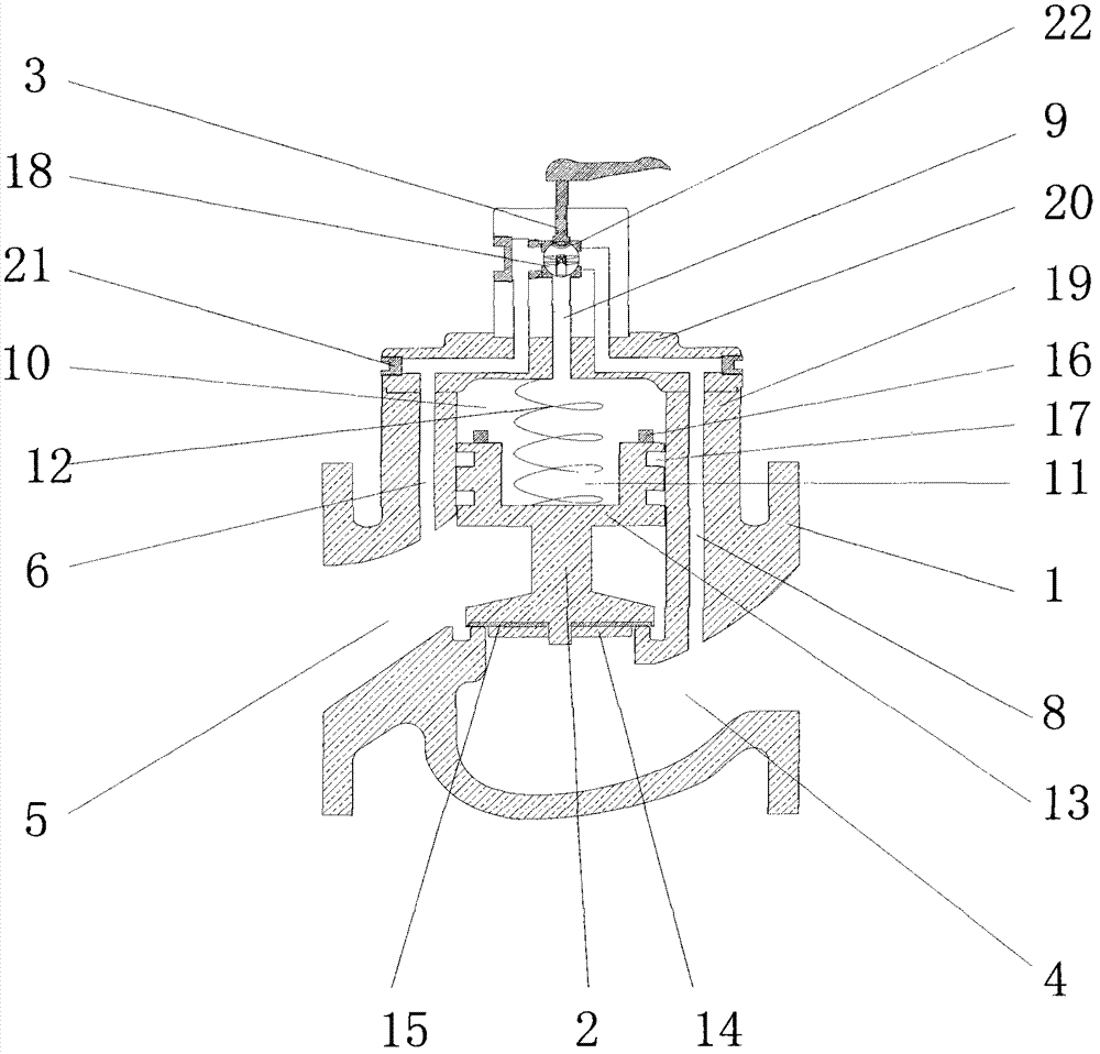
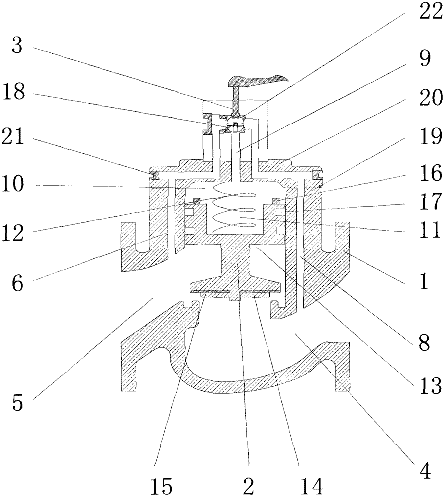
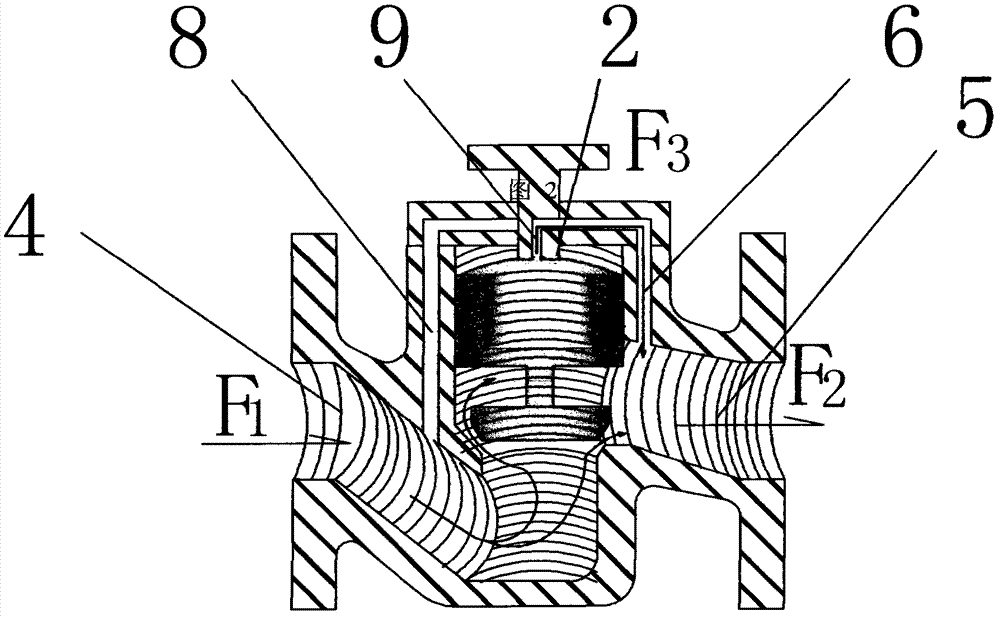
[0030] see Figure 1-Figure 9 As shown, a hydraulic booster valve includes a valve body 1 with a cavity, the valve body 1 includes a main valve body 19 and a valve cover 20, the main valve body 19 and the valve cover 20 are fixed by sealing screws 21, and are slidably set The spool 2 in the valve body 1 includes a spool main body 13, a gasket fixing frame 14 and a sealing gasket 15, and a seal is installed between the valve core body 13 and the gasket fixing frame 14. Pad 15, the upper end of the spool main body 13 is provided with a stopper 16 so that a gap is provided between the upper end surface of the spool ...


PUM


Abstract

The invention discloses a hydraulic boosting valve which comprises a valve body, a valve core and a valve rod, wherein the valve body is provided with a containing cavity, the valve core is slidably arranged in the valve body, the valve rod is rotatably arranged on the valve body, the valve body is arranged below the valve rod and is respectively provided with a water inlet channel and a water outlet channel which are communicated, and the valve core is positioned between the water inlet channel and the water outlet channel. The hydraulic boosting valve has two operating states, the first operating state refers to an off state while the second operating state refers to an on state, and the hydraulic boosting valve has a third operating state referring to a pressure reducing and pressure stabilizing state. At the third operating state, a first channel, a second channel and a third channel are communicated with one another by the aid of the three-way valve core, and the valve rod rotates to enable the three-way valve core to rotate so that the water inlet areas of the first channel and the second channel are adjusted, and then the hydraulic boosting valve is positioned at the third operating state, namely, the pressure reducing and pressure stabilizing state. The hydraulic boosting valve is simple in structure, reasonable in design, light, rapid and stable in on and off and stable in pressure reduction and pressure stabilization.

Description

technical field [0001] The invention is a valve, in particular to a hydraulic booster valve. Background technique [0002] Valves are widely used in daily life and industrial production, mainly composed of valve body, valve stem, valve core and so on. Traditional valves are adjusted manually. In the process of adjusting the switch, manpower is required to overcome the pressure of the fluid. For large valves, it is often necessary to use a wrench, tools to open or manually open. Many valves exceeding DN100 are equipped with deceleration equipment. The cost is high, the volume is large, the closing force is large, the valve is difficult to close, the labor intensity is high, the switch wears quickly every time, and it is inconvenient to use. [0003] The inventor applied for a booster valve patent on June 23, 2006, and obtained a utility model patent on August 1, 2007. The patent number is ZL200620074469.0. After three years of actual use, it was found that the valve core was...

Claims


Application Information

Patent Timeline
Patent Type & Authority Applications(China)
IPC IPC(8): F16K31/00F16K27/02F16K11/087
Inventor 金哲龙
Owner 金哲龙
Why Eureka
Try Eureka