Backlight module and display device

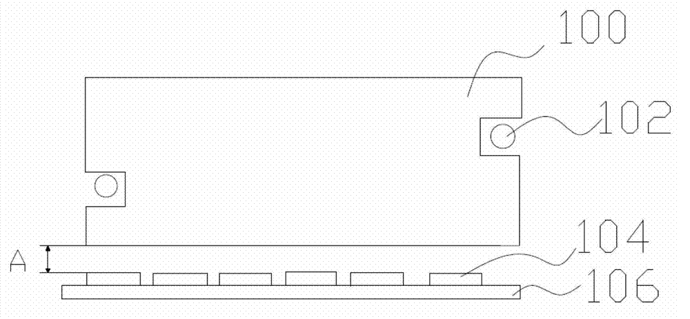
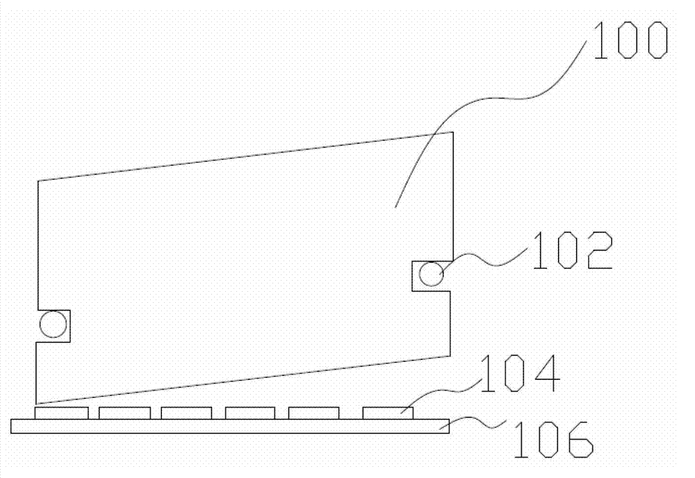
A technology for a backlight module and an adjustment device, which is applied to identification devices, lighting devices, fixed lighting devices, etc., can solve the problems of inconsistent spacing, collision, damage to the light guide plate 100 and the LED 104, etc., and achieve the effect of preventing optical problems.

Inactive Publication Date: 2012-11-07
DARWIN PRECISIONS SUZHOU CORP
View PDF5 Cites 3 Cited by
  • Summary
  • Abstract
  • Description
  • Claims
  • Application Information

AI Technical Summary

Problems solved by technology

like figure 1 As shown, 100 is a light guide plate, 102 is a rivet, 104 is an LED, and 106 is a circuit board, wherein the light guide plate 100 is fixed on the backplane (not shown) by the rivet 102, and the distance between the LED 104 and the light guide plate 100 is A. Ideally, the distance between the LED 104 and the points of the light guide plate 100 is consistent, but when the rivet 102 is skewed or the size of the light guide plate 100 is cut irregularly, the distance between the LED 104 and the points of the light guide plate 100 will be inconsistent, such as Figure 1a As shown, it will seriously affect the optical effect of the backlight module. For example, when the distance between the LED 104 and the light guide plate 100 is too small, the light guide plate 100 will collide with the LED 104 after expansion, thereby damaging the light guide plate 100 and the LED 104; If the distance between the LED 104 and the light guide plate 100 is too large, the brightness in the middle of the backlight module will be poor; if the distance between the LED 104 and the points of the light guide plate 100 is uneven, the brightness of the backlight module will be uneven.

Method used


Image

  • Backlight module and display device
  • Backlight module and display device
  • Backlight module and display device

Examples


Embodiment Construction

[0027] In order to have a further understanding of the purpose, structure, features, and functions of the present invention, the following detailed descriptions are provided in conjunction with the embodiments.

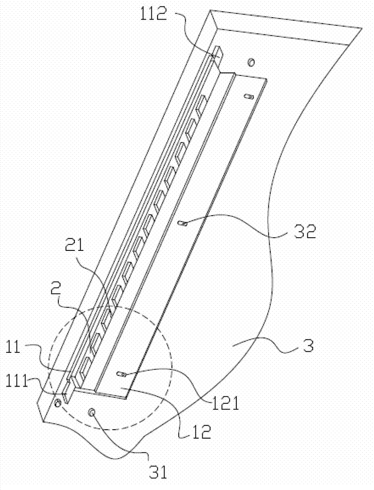
[0028] Such as figure 2 Shown is a schematic diagram of a part of the structure of the backlight module of the present invention. Figure 2a for figure 2 The enlarged schematic diagram of the middle part. The backlight module includes a backplane 3, a first heat dissipation plate 11 and a light source 21, the first heat dissipation plate 11 is arranged on the backplane 3, the first heat dissipation plate 11 has fixing parts 111, 112; the light source 21 is arranged on the on the first cooling plate 11. Such as image 3 Shown is a schematic diagram of the structure of the first compartment of the backlight module of the present invention. The backlight module further includes a light guide plate 7 disposed on one side of the light source 21 , and there is a firs...


PUM


Abstract

The invention provides a backlight module and a display device. The backlight module comprises a back panel, a first radiating plate, a light source, a light guide plate and a regulating device, wherein the first radiating plate is arranged on the back panel, and provided with a fixed part; the light source is arranged on the first radiating plate; the light guide plate is arranged at one side of the light source, and a first interval is arranged between the light guide plate and the light source; the regulating device is provided with a first regulating part and a second regulating part, the first regulating part is provided with a first toothed part, the second regulating part is provided with a second toothed part, and the first and second toothed parts are mutually contacted; the first regulating part and the fixed part are fixedly and mutually arranged; the second regulating plate is fixed on the back panel, so that the first and second regulating parts are in close fit in the direction perpendicular to the back panel; and the position of the first radiating plate is regulated through mutual movement of the first and second toothed parts in the direction parallel to the back panel, namely the first internal is regulated so as to be capable of flexibly regulating the space between the light source and the light guide plate.

Description

technical field [0001] The invention relates to the field of display devices, in particular to a backlight module with an adjusting device. Background technique [0002] At present, the light guide plate in the backlight module is fixed by rivets on the back plate. Such as figure 1 As shown in FIG. 2 , it is a schematic structural diagram of a conventional backlight module. Such as figure 1 As shown, 100 is a light guide plate, 102 is a rivet, 104 is an LED, and 106 is a circuit board, wherein the light guide plate 100 is fixed on the backplane (not shown) by the rivet 102, and the distance between the LED 104 and the light guide plate 100 is A. Ideally, the distance between the LED 104 and the points of the light guide plate 100 is consistent, but when the rivet 102 is skewed or the size of the light guide plate 100 is cut irregularly, the distance between the LED 104 and the points of the light guide plate 100 will be inconsistent, such as Figure 1a As shown, it will ...

Claims


Application Information

Patent Timeline
IPC IPC(8): F21S8/00F21V17/02G09F9/33F21Y101/02
Inventor 陈森元和雪芹
Owner DARWIN PRECISIONS SUZHOU CORP
Why Eureka
Try Eureka