
Cooling device in high-vacuum distillation system

A distillation system and cooling device technology, applied in vacuum distillation, steam/vapor condensers, lighting and heating equipment, etc., can solve problems such as hindering machine operation, damaging pump body, polluting the environment, etc., to reduce product volume and reduce cleaning Frequency, the effect of protecting the environment

Inactive Publication Date: 2012-11-07
山东盛华电子新材料有限公司
View PDF8 Cites 4 Cited by
  • Summary
  • Abstract
  • Description
  • Claims
  • Application Information

AI Technical Summary

Problems solved by technology

[0002] At present, when solid products are distilled in high vacuum, water jet-Roots vacuum unit or rotary vane vacuum pump is used to provide a vacuum of no more than 100Pa for high vacuum distillation. However, in this low-pressure environment, some products are easy to sublimate, enter the vacuum unit, and condense Adhering to the rotor or vane, hindering the operation of the machine, or even clogging and damaging the pump body, and part of it is discharged with the gas, polluting the environment

Method used


Image

  • Cooling device in high-vacuum distillation system
  • Cooling device in high-vacuum distillation system

Examples


Embodiment 1

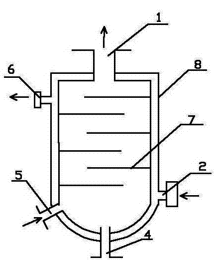
[0012] Embodiment 1, a cooling device in a high vacuum distillation system, with reference to figure 1 , the housing 8 is a double-layer hollow housing, the lower part of the hollow housing 8 is provided with a water inlet 2, and the upper part is provided with a water outlet 6, and the middle cavity between the water inlet 2 and the water outlet 6 and the hollow housing 8 Connected, the top of the housing 8 is provided with an air outlet 1, and the lower part is provided with an air inlet 5, the air inlet 5 and the air outlet 1 communicate with the inner cavity of the housing 8, and the upper part of the inner cavity of the housing 8 is provided with a gas baffle 7. The bottom of the casing 8 is provided with a discharge port 4 communicating with the inner cavity of the casing, which constitutes a structure of the present invention.

Embodiment 2

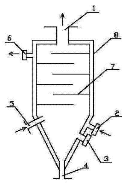
[0013] Embodiment 2, a cooling device in a high vacuum distillation system, with reference to figure 2 , on the basis of Embodiment 1, the upper part of the housing 8 is cylindrical, the lower part is conical, the discharge port 4 is arranged at the tip of the conical housing 8, and the lower part of the housing 8 is provided with an observable housing The inner sight mirror 3, the openings between the adjacent gas baffles 7 and the inner wall of the housing 8 are arranged in a staggered manner, and the others are completely the same as in the first embodiment.


PUM


Abstract

The invention discloses a cooling device in a high-vacuum distillation system. The cooling device consists of a casing, an air outlet, an air inlet and a discharging port. The casing is a double-layer hollow casing, the lower portion of the hollow casing is provided with a water inlet, the upper portion of the hollow casing is provided with a water outlet, the water inlet and the water outlet are communicated with a middle cavity of the hollow casing, and the upper portion in the casing is provided with an air blocking plate. The cooling device has the advantages of being simple in structure, recovering products and protecting vacuum devices through shock cooling.

Description

technical field [0001] The invention belongs to the technical field of chemical equipment, and in particular relates to a cooling device in a high vacuum distillation system. Background technique [0002] At present, when solid products are distilled in high vacuum, water jet-Roots vacuum unit or rotary vane vacuum pump is used to provide a vacuum of no more than 100Pa for high vacuum distillation. However, in this low-pressure environment, some products are easy to sublimate, enter the vacuum unit, and condense Adhering to the rotor or rotating vane, it hinders the operation of the machine, or even blocks and damages the pump body, and part of it is discharged with the gas, polluting the environment. Contents of the invention [0003] The purpose of the present invention is to improve the deficiencies of the prior art and provide a cooling device in a high-vacuum distillation system that has a simple structure, recovers products through quenching, and protects vacuum equi...

Claims


Application Information

Patent Timeline
Patent Type & Authority Applications(China)
IPC IPC(8): F28B1/02B01D3/10
Inventor 谢英王作鹏王金荣吕勇达任国旭
Owner 山东盛华电子新材料有限公司
Learn More