Louver fin and heat exchanger adopting louver fins

A technology of louver fins and heat exchangers is applied in the field of fins of heat exchangers, which can solve the problems of the reduction of the energy efficiency ratio of the tube-fin heat exchangers, the easy blockage of the openings of the louvers, and the decrease of the heat exchange capacity of the products, and achieves the Significant economic and social benefits, simple structure, and the effect of saving electricity

Active Publication Date: 2012-11-07
珠海盾安热工科技有限公司
View PDF7 Cites 13 Cited by
  • Summary
  • Abstract
  • Description
  • Claims
  • Application Information

AI Technical Summary

Problems solved by technology

In the field of household / commercial air conditioning, due to the low head-on wind speed of the heat exchanger, generally 1.5m / s~2.5m / s, compared with traditional heat exchangers, micro-channel heat exchangers are more prone to dust blockage, especially when the shutters are opened. The window is more likely to be blocked, which leads to a sharp drop in the heat transfer capacity of the product
The experimental results show that, in the usual use environment in my country, after two months, the dust accumulation will cause the energy efficiency ratio of the system to drop by 10%; The energy efficiency ratio of the plate heat exchanger is only reduced by 1.5%

Method used


Image

  • Louver fin and heat exchanger adopting louver fins
  • Louver fin and heat exchanger adopting louver fins
  • Louver fin and heat exchanger adopting louver fins

Examples


Embodiment 1

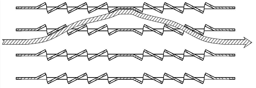
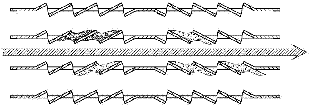
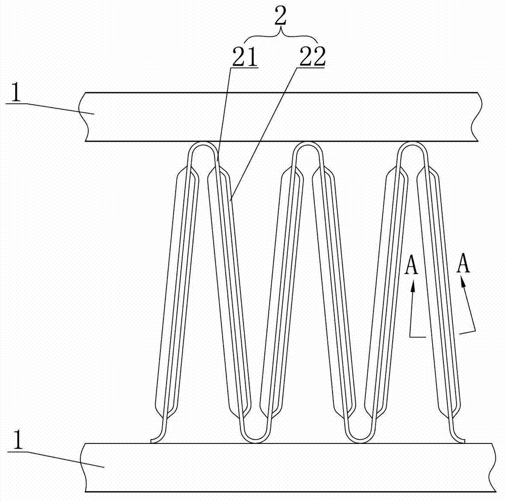
[0033] refer to Figure 4 , 5 , the louver fin of the present embodiment includes a substrate 21 and a window fin 22 formed on the substrate 21, an airflow channel 3 is formed between adjacent window fins 22, and the substrate 21 is divided into inlet portions 23 according to the air flow direction , windward part 24, reversing part 25, leeward part 26 and outlet part 27, above-mentioned window fin 22 is formed in windward part 24 and leeward part 26, and the window wing 22 window opening angle α of windward part 24 and the window of leeward part 26 The fins 22 have the same window opening angle β, and the window opening directions are opposite, and the inlet portion 23 is provided with a guide protrusion 28 . Generally, the airflow enters the fins from the inlet 23, and after passing through the guide protrusions 28, most of the dust in the air is blocked or bounced off, and the bounced dust directly enters the direct airflow, and the airflow bypasses the guide After the fl...

Embodiment 2

[0039] refer to Figure 6, the solution of this embodiment is substantially the same as that of Embodiment 1, except that: the diversion protrusion 28 is V-shaped, similarly, the V-shaped diversion protrusion also has two slopes, its effect can refer to Embodiment 1.

Embodiment 3

[0041] refer to Figure 7 , the scheme of this embodiment is roughly the same as that of Embodiment 1, the difference is that the diversion protrusion 28 is arc-shaped, and similarly, although the arc-shaped diversion protrusion does not have a slope, its arc surface can also reach The technical effect of the trapezoidal diversion protrusion in the first embodiment.

[0042] From the description of the above embodiment, it can be known that the shape of the diversion protrusion 28 includes but is not limited to arc shape, V shape or trapezoid, and can also be other shapes, such as square, etc., but in terms of effect, it has a slope or an arc surface. The implementation effect of the deflector protrusion is better.


PUM


Abstract

The invention discloses a louver fin and a heat exchanger adopting the louver fins, in particular to a microchannel heat exchanger, and solves the technical problem that fins of the conventional heat exchanger have high possibility of ash clogging, resulting in lowered performances of the heat exchanger. The louver fin provided by the invention includes a base sheet and louvered fins formed on the base sheet, wherein an air flow passage is formed between the adjacent louvered fins; and flow guide projections are arranged on the base sheet, and correspond to air inlets of the air flow passages. The louver fin provided by the invention can be applied to various heat exchangers and microchannel heat exchangers in the field of household/commercial air conditioners, can remarkably improve the ash accumulation of the air side of the heat exchanger, and improves the heat exchange performance of heat exchangers, particularly the microchannel heat exchangers.

Description

technical field [0001] The invention relates to a heat exchanger, especially a fin of the heat exchanger. Background technique [0002] The micro-channel heat exchanger is a high-efficiency heat exchanger. Its flat tube adopts a micro-channel structure. Compared with the existing ordinary heat exchanger, the micro-channel heat exchanger can strengthen condensation and boiling heat transfer, and significantly improve the refrigerant side exchange rate. Thermal efficiency. In order to improve the heat exchange performance, fins are usually provided between the flat tubes of the heat exchanger. The micro-channel heat exchanger has the advantages of light weight, compact structure, and high heat exchange efficiency. It can replace copper materials (national strategic reserve resources) and has cost advantages; at the same time, its small internal volume is conducive to greatly reducing refrigerant charging. It is in line with the trend of energy saving and environmental protec...

Claims


Application Information

Patent Timeline
Patent Type & Authority Applications(China)
IPC IPC(8): F28F1/32F25B39/00
Inventor 葛方根施骏业朱兴军
Owner 珠海盾安热工科技有限公司
Why Eureka
Try Eureka