Pulse power source based on LTD (Laser Target Designator) self-synchronizing switch

A technology of pulse power source and self-synchronization, applied in the field of pulse power, can solve the problem of difficult synchronization of LTD multi-switches, and achieve the effect of simple and reliable synchronization process, low energy loss, and reliable high-voltage pulse output.

Inactive Publication Date: 2012-11-07
ZHEJIANG UNIV
View PDF3 Cites 11 Cited by
  • Summary
  • Abstract
  • Description
  • Claims
  • Application Information

AI Technical Summary

Problems solved by technology

[0005] Aiming at the above-mentioned technical defects existing in the prior art, the present invention provides a pulse power source based on LTD self-synchronizing switch, which can solve the problem of difficult synchronization of traditional LTD multi-switches and realize reliable high-voltage pulse output

Method used


Image

  • Pulse power source based on LTD (Laser Target Designator) self-synchronizing switch
  • Pulse power source based on LTD (Laser Target Designator) self-synchronizing switch
  • Pulse power source based on LTD (Laser Target Designator) self-synchronizing switch

Examples


Embodiment 1

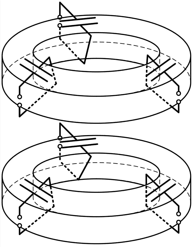
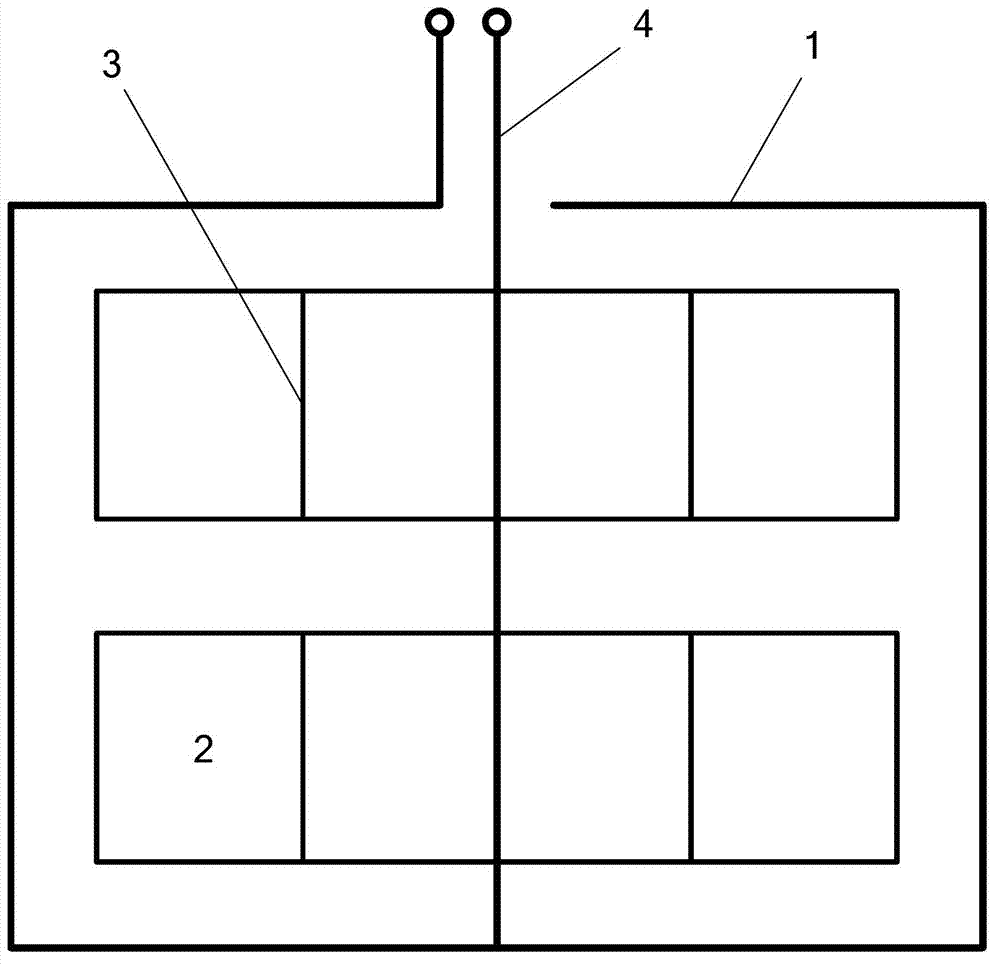
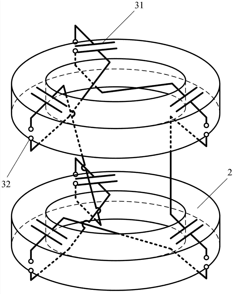
[0025] like figure 2 and Figure 4 As shown, a pulse power source based on an LTD self-synchronous switch, including an outer conductor; the outer conductor includes a conductor box 1 and a conductor bar 4, and the conductor box 1 is provided with two magnetic rings 2, and the two magnetic rings 2 are stacked concentrically Arranged and there is a gap between the two magnetic rings 2 ; the conductor bar 4 is vertically arranged at the bottom of the conductor box 1 and extends out of the conductor box 1 after penetrating the two magnetic rings 2 .

[0026] In this embodiment, the magnetic ring 2 is a ferrite magnetic ring; the conductor box 1 is a hollow metal cylinder, and the top of the cylinder is provided with a through hole for the conductor bar 4 to protrude; the conductor bar 4 extends out of one end of the conductor box 1 It is connected to one end of the resistive load 6 , and the other end of the resistive load 6 is connected to any point on the edge of the through ...

Embodiment 2

[0032] like figure 2 and Figure 5 As shown, a pulse power source based on an LTD self-synchronous switch, including an outer conductor; the outer conductor includes a conductor box 1 and a conductor bar 4, and the conductor box 1 is provided with two magnetic rings 2, and the two magnetic rings 2 are stacked concentrically Arranged and there is a gap between the two magnetic rings 2 ; the conductor bar 4 is vertically arranged at the bottom of the conductor box 1 and extends out of the conductor box 1 after penetrating the two magnetic rings 2 .

[0033] In this embodiment, the magnetic ring 2 is an amorphous magnetic ring; the conductor box 1 is a hollow metal cylinder, and the top of the cylinder is provided with a through hole for the conductor rod 4 to protrude; The load 6 is connected, and one end extending from the conductor box 1 is connected to one end of the inner layer conductor of the variable impedance line 5, the other end of the inner layer conductor of the va...


PUM


Abstract

The invention discloses a pulse power source based on an LTD (Laser Target Designator) self-synchronizing switch. The pulse power source comprises an epibolic conductor which comprises a conductor box and a conductor rod; wherein the conductor box is provided with a plurality of magnetic rings; the conductor rod is vertically placed at the bottom of the conductor box and penetrates through all the magnetic rings and then extends out of the conductor box; a plurality of discharge branches are wound on the magnetic ring and are serially connected to form a discharge link circuit; a plurality of discharge link circuits are connected in series and then are connected end to end to form a closed ring discharge loop; the discharge branch is formed by connecting an energy storage apparatus and a switch connected in series. The pulse power source is based on the traditional LTD basic structure, so that a plurality of discharge branches are serially connected, one switch is conducted to automatically trigger the other switches to synchronously overvoltage conduct, the complex external trigger devices are not needed, so that the synchronous process is simple and reliable; the reliable high voltage pulse output can be obtained through the multi-switch cooperative work, and the energy consumption is low.

Description

technical field [0001] The invention belongs to the technical field of pulse power, and in particular relates to a pulse power source based on an LTD self-synchronizing switch. Background technique [0002] Pulse power technology is an emerging technology that compresses energy in space and time, and releases the energy stored for a long time in a very short time to produce specific physical or chemical effects. It is widely used in military, exploration, Medical, energy, environment and other fields. [0003] Conventional pulse power sources include multiple capacitive energy storage devices. By charging the energy storage devices at high voltage, the energy is compressed in space, and the energy is compressed in time by the fast conduction discharge of the closed switch. In recent years, LTD (Linear Transformer Driver, linear transformer drive source) has become the international pulse power drive source technology due to its characteristics of short rising edge of pulse ...

Claims


Application Information

Patent Timeline
Patent Type & Authority Applications(China)
IPC IPC(8): H02M9/00
Inventor 刘振王秉哲闫克平邓官垒
Owner ZHEJIANG UNIV
Why Eureka
Try Eureka