
Suction nozzle for vacuum cleaner

A vacuum cleaner and suction hole technology, applied in the direction of vacuum cleaners, suction nozzles, carpet cleaning, etc., can solve the problems of less vibration of the device, little noise, and little effect of foreign objects, and achieve the effect of increasing the amount of vibration

Inactive Publication Date: 2012-11-07
LG ELECTRONICS INC
View PDF5 Cites 4 Cited by
  • Summary
  • Abstract
  • Description
  • Claims
  • Application Information

AI Technical Summary

Problems solved by technology

[0008] However, such a device for removing dust and foreign matter has little effect of raising fine dust and foreign matter that exist on the surface to be cleaned of bedding such as carpets or quilts due to its weak vibration amount and vibration force. question
[0009] In particular, since home appliances such as vacuum cleaners are used in North American countries with a supply of 110 volts, the number of rotations per minute (RPM) of the suction motor inside the main body is lower than that in Korea, which further reduces the performance of the above-mentioned fans.
[0010] And, for the device for removing dust and foreign matter, there is a problem that the amount of vibration of the device for removing dust and foreign matter is small because the above-mentioned cam reciprocates once when the fan rotates once.
[0011] On the other hand, since the device for removing dust and foreign matter is placed on the outer surface of the suction nozzle of the vacuum cleaner and vibrates, there is a problem that the device collides with the suction nozzle during cleaning and generates noise.

Method used


Image

  • Suction nozzle for vacuum cleaner
  • Suction nozzle for vacuum cleaner
  • Suction nozzle for vacuum cleaner

Examples


Embodiment Construction

[0031] Hereinafter, embodiments of the present invention will be described in detail with reference to the accompanying drawings. In this process, the size, shape, etc. of the structural elements shown in the drawings may be enlarged for clarity and convenience of description. In addition, the terms specifically defined in consideration of the structure and operation of the present invention may differ according to the user's or the user's intention or practice. Definitions of such terms should be based on the entirety of this specification.

[0032] Moreover, the concept of the present invention is not limited to the proposed embodiments, and those skilled in the art who understand the concept of the present invention can easily implement other embodiments within the scope of the same concept, which of course also belong to the scope of the present invention.

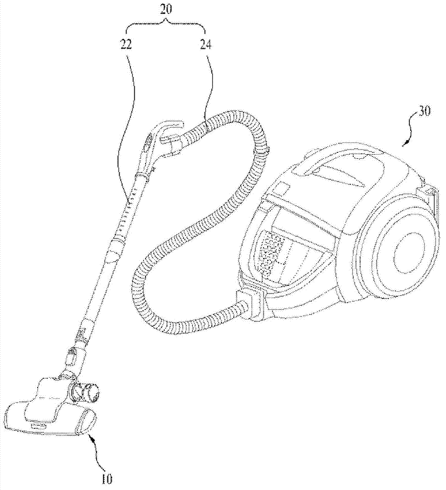
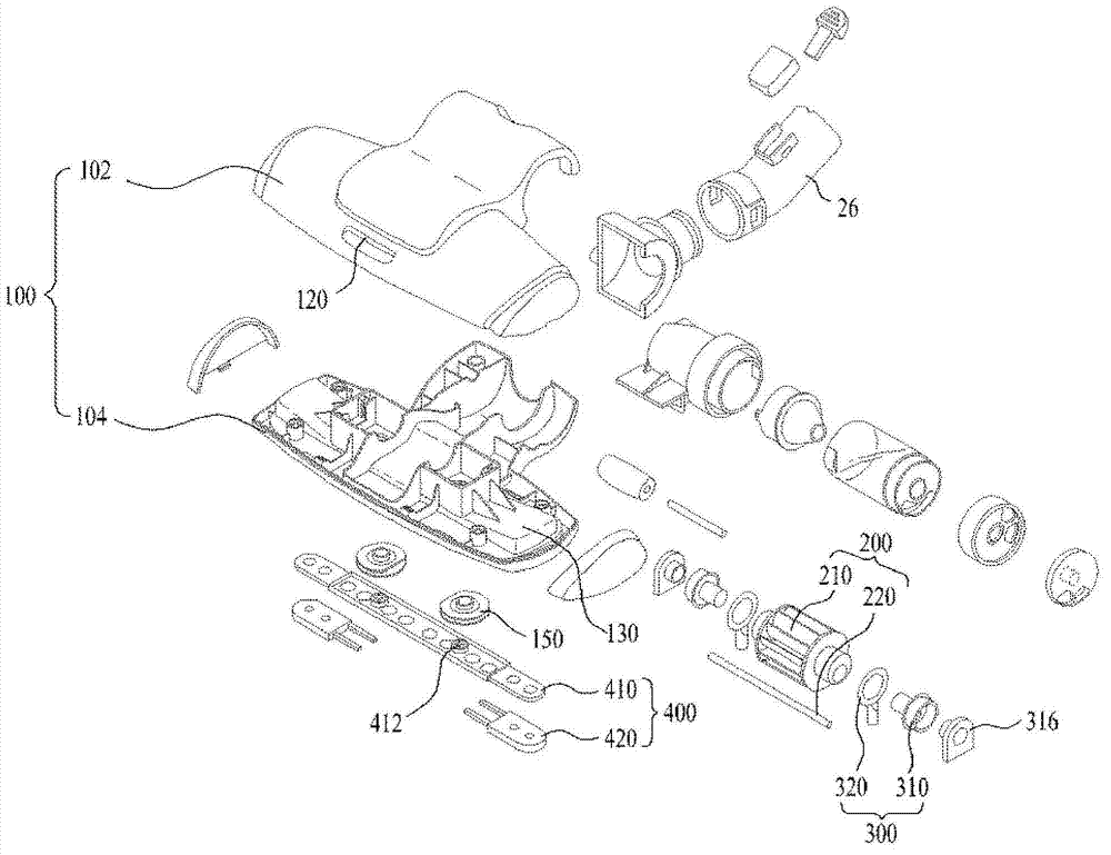
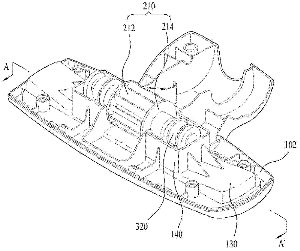
[0033] figure 1 is a perspective view of a vacuum cleaner according to an embodiment of the present invention. re...


PUM


Abstract

The present invention relates to a suction nozzle for a vacuum cleaner, which comprises: a case member, which has suction holes to aspirate dust and inlet holes through which air is let in; a rotary member, which is provided in the case member and rotates by the air that is let in through the suction holes and the inlet holes; a power transmission member, which transforms the rotary movement of the rotary member to a linear reciprocating motion; and a punching member, which connects to the power transmission member, wherein the power transmission member includes a cam shaft, which is coupled to the rotary member, and has a phase difference therebetween, and a cam, which connects to the cam shaft. The present invention increases vibrating force and amount and prevents noise occurrence during cleaning.

Description

technical field [0001] The present invention relates to a suction nozzle of a vacuum cleaner, and more particularly to a suction nozzle of a vacuum cleaner in which camshafts of a power transmission part located inside the suction nozzle of the vacuum cleaner have a phase difference from each other. Background technique [0002] Generally, a vacuum cleaner is a device that uses a suction motor installed inside the main body to suck dust and foreign objects together with the air and then filter them inside the main body. [0003] Vacuum cleaners having the above-mentioned functions are generally classified into a cylinder type in which a mouth serving as a suction port communicates with a main body through a connecting pipe, and an upright type in which the mouth is integrated with the main body. [0004] The cylinder vacuum cleaner includes: a vacuum cleaner body, which contains a suction motor that generates suction force, etc., a suction nozzle, which sucks dust and foreig...

Claims


Application Information

Patent Timeline
Patent Type & Authority Applications(China)
IPC IPC(8): A47L9/04A47L13/36
CPCA47L9/0483A47L9/0416A47L9/02A47L9/04A47L11/20
Inventor 黄正培黄满泰
Owner LG ELECTRONICS INC
Learn More