Chain tensioner

A tensioner and chain technology, which is applied in the direction of belts/chains/gears, mechanical equipment, transmission devices, etc., can solve the problem of identifying whether the initial positioning is released at a glance

Active Publication Date: 2015-05-20
NTN CORP
View PDF9 Cites 1 Cited by
  • Summary
  • Abstract
  • Description
  • Claims
  • Application Information

AI Technical Summary

Problems solved by technology

[0013] However, with this chain tensioner, since the positioning clip is not removed when the initial positioning is released, it is difficult to distinguish at a glance whether the initial positioning is released.
Therefore, after installing the chain tensioner to the engine, there is a possibility of installing the engine cover in the state of forgetting to release the initial positioning.

Method used


Image

  • Chain tensioner
  • Chain tensioner
  • Chain tensioner

Examples


Embodiment Construction

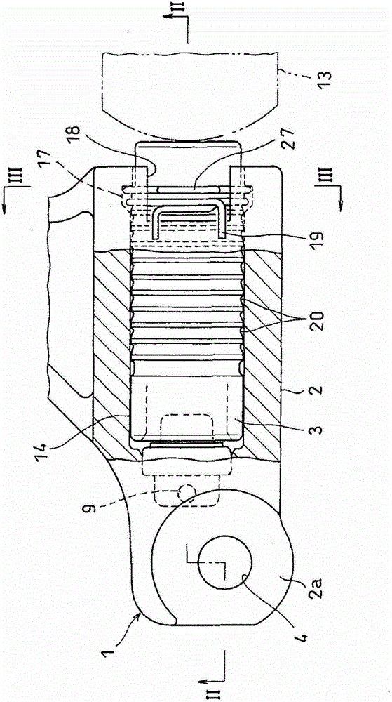
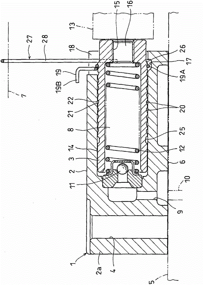
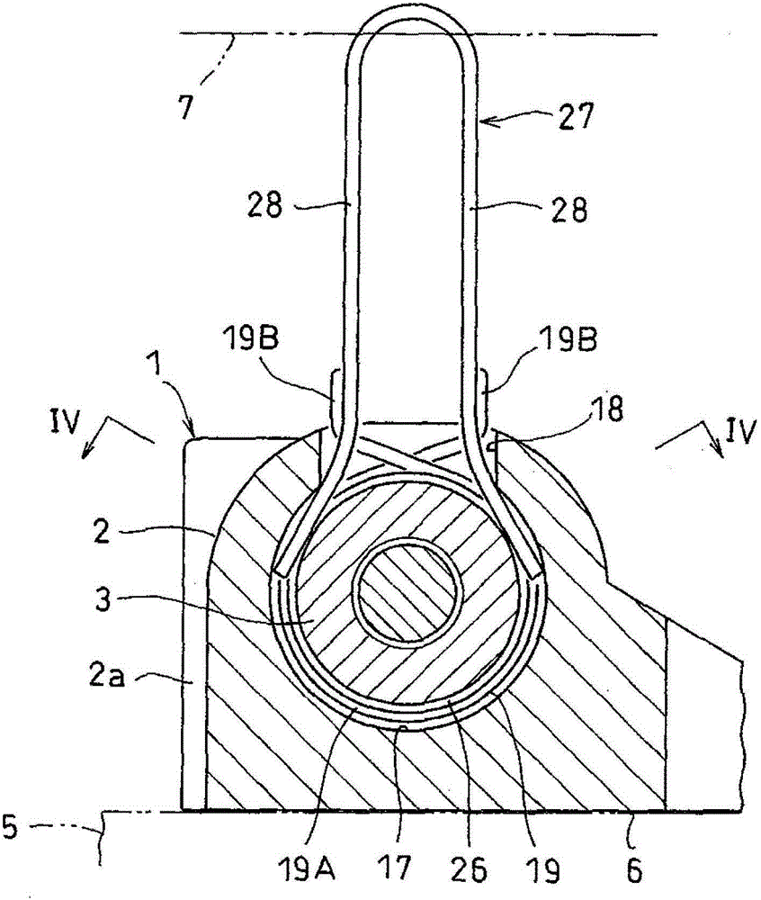
[0033] figure 1 The chain tensioner 1 which concerns on 1st Embodiment of this invention is shown. This chain tensioner 1 has a cylindrical cylinder 2 with one end open and the other end closed, and a plunger 3 inserted into the cylinder 2 so as to be slidable in the axial direction. The cylinder 2 is fixed to the side surface of the engine block 5 by screwing bolts (not shown) into the bolt insertion holes 4 of the mounting piece 2 a integrally formed with the cylinder 2 .

[0034] Such as figure 2 As shown, on the outer circumference of the cylinder 2, a support surface 6 supported on the side surface of the engine block 5 is formed. An engine cover 7 is attached to the engine body 5 so as to face a side surface of the engine body 5 with the chain tensioner 1 interposed therebetween. The cylinder 2 is made of aluminum in order to reduce the weight of the engine, and is molded by die-casting in order to reduce the manufacturing cost.

[0035]The plunger 3 is formed in a ...


PUM


Abstract

Disclosed is a chain tensioner in which the accidental cancellation of an initial setting as a result of vibration and impact during transport does not easily occur, and in which cancellation of the initial setting after installation in an engine is not easily forgotten. The chain tensioner (1) is provided with a cylinder (2), a plunger (3) that is slidably inserted within the cylinder (2), and a return spring (12) that impels the plunger (3), and absorbs variations in the tension of the chain by means of the movement of the plunger (3) in the axial direction, wherein a setting groove (17) and a helix (18) are provided on the opening edge of the cylinder (2), the edges of the arms (28) of a forked setting pin (27) are inserted from the helix (18) into a space between the setting groove (17) and the outer periphery of the plunger (3), and a stepped section (26), which restricts the movement of the plunger (3) in the projecting direction by latching with the inserted arms, is provided on the outer periphery of the plunger (3).

Description

technical field [0001] The present invention relates to a chain tensioner for maintaining the tension of a timing chain driving a camshaft of an automobile engine. Background technique [0002] Generally, in an automobile engine, the rotation of the crankshaft is transmitted to the camshaft via a timing chain, and the valves of the combustion chambers are opened and closed by the rotation of the camshaft. Here, in order to keep the tension of the chain within an appropriate range, a tension adjusting device is often used, that is, the tension adjusting device is provided with a chain guide swingably centered on a fulcrum axis, and a chain guide that presses the chain toward the chain. The chain tensioner of the piece constitutes. [0003] As a chain tensioner incorporated into the tension adjustment device, there is known a chain tensioner which has a cylinder with one end open and the other end closed; a plunger; a return spring biasing the plunger in a direction protrudi...

Claims


Application Information

Patent Timeline
Patent Type & Authority Patents(China)
IPC IPC(8): F16H7/08
CPCF16H7/0836F16H2007/0806F16H2007/0812F16H2007/0853F16H2007/0855F16H2007/0859F16H2007/0878
Inventor 北野聪鬼丸好一
Owner NTN CORP
Why Eureka
Try Eureka