Composition (floor) slab of steel bar welding orthogonal net rack and concrete

An orthogonal and concrete technology, which is applied in the processing of floors, building materials, structural elements, etc., can solve the problems of overall collapse of cast-in-place slabs, layer-by-layer support and formwork, etc.

Inactive Publication Date: 2012-11-14
陈云波
View PDF0 Cites 6 Cited by
  • Summary
  • Abstract
  • Description
  • Claims
  • Application Information

AI Technical Summary

Problems solved by technology

In the past few decades, many people have made technical inventions on supports and formwork, and have achieved certain results, but support and formwork are still needed, and there have been many accidents of overall collapse of cast-in-place slabs at home and abroad, so in key projects In the mid-term rebound, there is a phenomenon of layer-by-layer support and formwork

Method used


Image

  • Composition (floor) slab of steel bar welding orthogonal net rack and concrete
  • Composition (floor) slab of steel bar welding orthogonal net rack and concrete
  • Composition (floor) slab of steel bar welding orthogonal net rack and concrete

Examples


specific Embodiment approach 1

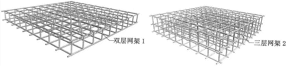
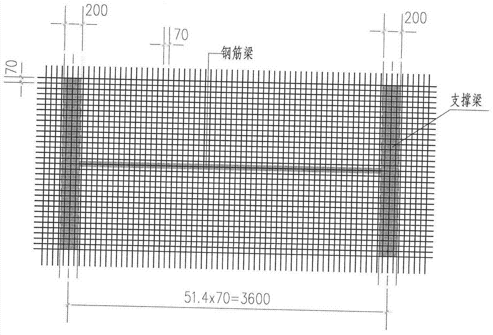
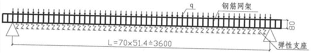
[0044] Specific implementation mode one: combine figure 1 Make a double layer and weld it with Q235Φ6 steel bars. The grid plane size is 70×70mm, and the plane layer height is 80mm. The orthogonal and vertical grid frame 1 is set on the beam, and then the decoration is made of type A and type B with hanging bars. slabs, aerated concrete and other lightweight concrete slabs are fixed on the grid as a permanent formwork. The method of type C is to wrap several layers of steel wire mesh at the bottom of the grid, subject to no leakage of grout, and then pour concrete above C20 without support and template.

specific Embodiment approach 2

[0045] Specific implementation mode two: combination figure 1 , according to the special requirements of the board, it can be made into a three-layer grid frame 2. The diameter of the steel bar can be from Φ6 to Φ10, which is more economical. The grid plane size is preferably from 50×50mm to 120×120mm. The slenderness ratio of the steel bar is ≥150. Set the grid frame on the beam, fix it on the grid frame with hanging bars according to the methods of Type A, Type B, and Type C, and then pour concrete larger than C20 to make a reinforced concrete cast-in-place floor slab that meets special requirements. No braces, no formwork.

specific Embodiment approach 3

[0046] Specific implementation method three: Reinforcement welded orthogonally placed grid frame and concrete composite (floor) slab Use hanging bars to fix the light concrete slab on the grid frame or fix the fireproof board on the grid frame or fix the insulation board on the grid frame In general, concrete greater than C20 is poured in the method of type A and type B. After solidification, it will be a high-quality anti-impact noise floor, or a floor with a high fire resistance level, or a floor with a high insulation level.


PUM


Abstract

The invention discloses a composition (floor) slab of a steel bar welding orthogonal net rack and concrete, reinforcement is realized through welding a net rack 1 or a net rack 2 by using rebars, so that the property that the traditional reinforced concrete plate is zero in bearing force before setting of concrete is thoroughly changed, and thus cast-in-place operation of the (floor) slab disclosed by the invention does not require templates and supports. From the situation that reinforcement of the net rack has bearing force before concrete setting, various decorative plates, insulation plates and anti-seismic noise plates can be developed to serve as permanent templates; and due to the principle that bending a plane to a curved surface can increase the rigidity of the plane, the net rack 1 or the net rack 2 is bent into a net rack 3, and various decorative plates, insulation plates and fire-proof plates are fixed on the inner side of the bent net rack 3 by using hanging bars. Concrete with the strength larger than C30 is sprayed in a layering mode. The design and construction of a shell can be greatly expanded by using the composition (floor) slab. As the composition (floor) slab conforms to favorable conditions described by modern three mechanical theories, the bearing force of the composition (floor) slab is increased, and the crack resistance and aseismicity are strengthened due to the strengthening of ductility of the composition (floor) slab.

Description

technical field [0001] The invention belongs to a building structure component, in particular to a (floor) slab and a shell combined with a steel bar welded orthogonal grid frame and concrete, which is a development and creation of a reinforced concrete slab. Background technique [0002] According to the earthquake records, among the factors that caused damage to people's lives in houses destroyed by the earthquake, damage to reinforced concrete floor slabs often caused damage to people's lives. The invention of reinforced concrete slabs at the beginning of the nineteenth century is an excellent invention recognized by the world: steel bars are homogeneous and high-strength, concrete has high compressive strength, and steel bars and concrete are solidified to form reinforced concrete slabs. Steel bars are mainly subjected to tension, and concrete is mainly subjected to compression. The two materials complement each other and complement each other. Therefore, for more than ...

Claims


Application Information

Patent Timeline
Patent Type & Authority Applications(China)
IPC IPC(8): E04B5/32E04C5/06E04G21/02
Inventor 陈云波
Owner 陈云波
Why Eureka
Try Eureka