Micro inertial measuring unit

A technology of micro-inertial measurement and range, applied in the field of inertial measurement, can solve the problems of gyroscope measurement error increase, decrease measurement accuracy, and affect navigation calculation, etc., and achieve the effect of reducing measurement error, improving measurement accuracy, and accurate measurement

Active Publication Date: 2012-11-14
TSINGHUA UNIV
View PDF6 Cites 32 Cited by
  • Summary
  • Abstract
  • Description
  • Claims
  • Application Information

AI Technical Summary

Problems solved by technology

[0004] There are two types of motion stages for micro-aircraft: stationary and maneuvering, and the traditional micro-inertial measurement combination (including a three-axis accelerometer and a three-axis gyroscope) cannot achieve acceleration measurements in different types of stages
If the large-range accelerometer is used alone, the resolution of the accelerometer is low, and the measurement accuracy is poor during the steady flight stage; if the small-range accelerometer is used alone, the resolution is high, the measurement accuracy

Method used


Image

  • Micro inertial measuring unit
  • Micro inertial measuring unit
  • Micro inertial measuring unit

Examples


Example Embodiment

[0041] The embodiments of the present invention are described in detail below. Examples of the embodiments are shown in the accompanying drawings, in which the same or similar reference numerals indicate the same or similar elements or elements with the same or similar functions. The embodiments described below with reference to the accompanying drawings are exemplary, and are intended to explain the present invention, but should not be construed as limiting the present invention.

[0042] In the description of the present invention, it should be understood that the terms "center", "longitudinal", "transverse", "length", "width", "thickness", "upper", "lower", "front", " "Back", "Left", "Right", "Vertical", "Horizontal", "Top", "Bottom", "Inner", "Outer", "Clockwise", "Counterclockwise" and other directions or positions indicated The relationship is based on the orientation or positional relationship shown in the drawings, which is only for the convenience of describing the prese...


PUM


Abstract

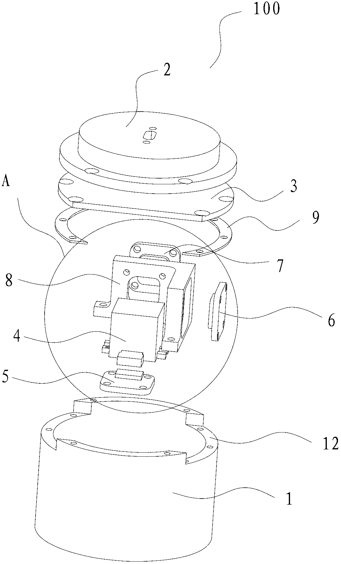
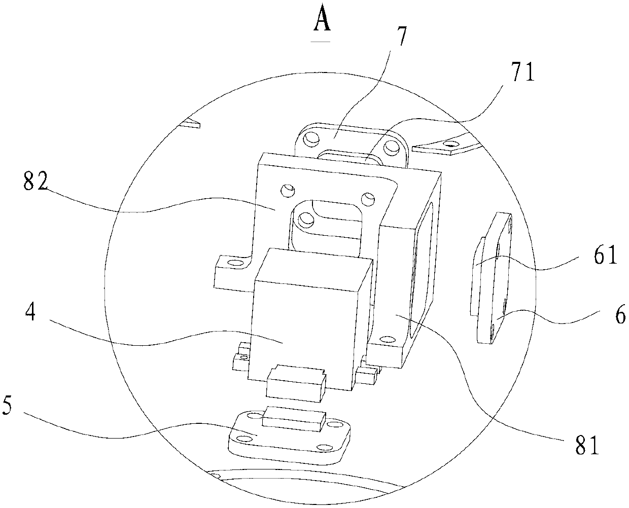
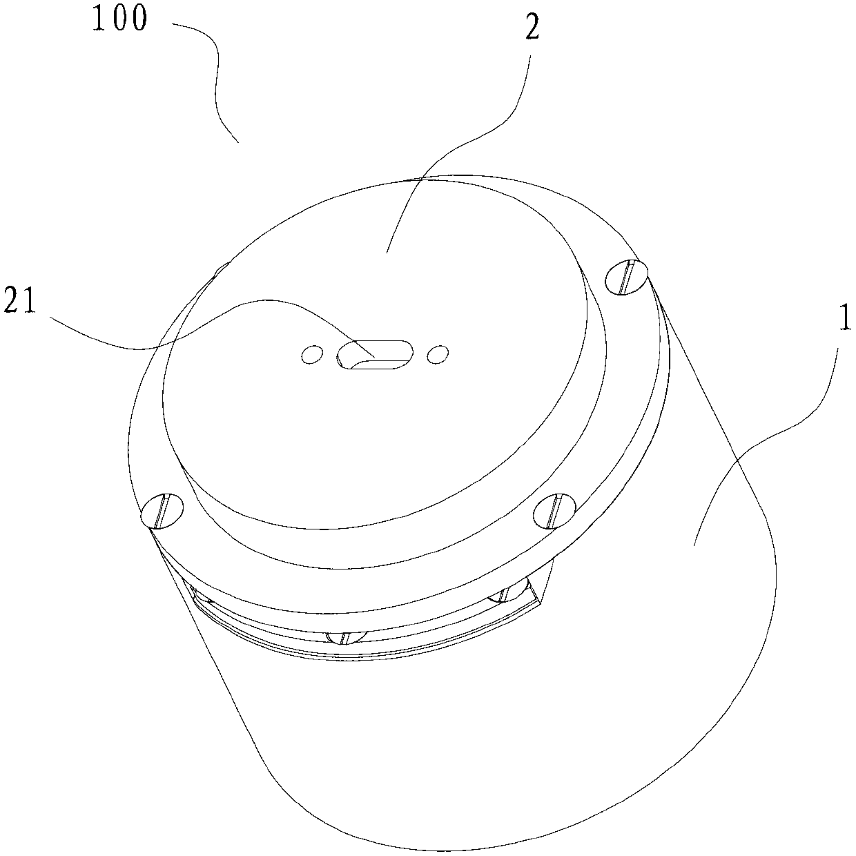
The invention discloses a micro inertial measuring unit which comprises a shell, a top cover, a main circuit board, a micro inertial measurement combination, a first double-shaft micro-machined accelerometer and a second double-shaft micro-machined accelerometer, wherein the top cover is arranged on the top end of the shell, a cavity is limited by the top cover and the shell, the main circuit board is arranged in the cavity, the micro inertia measurement combination is arranged in the cavity and is connected with the main circuit board, the micro inertia measurement combination comprises a three-shaft micro-machined gyroscope, a three-shaft micro-machined accelerometer and a three-shaft magnetometer; and the first double-shaft micro-machined accelerometer and the second double-shaft micro-machined accelerometer are respectively arranged in the cavity and respectively connected with the main circuit board. The micro inertial measuring unit can be used for measuring motion parameters of a small aircraft under a high-dynamic and large-overload motion state, and calculating a motion attitude and a motion track of the small aircraft.

Description

technical field [0001] The invention relates to the field of inertial measurement, in particular to a micro-inertial measurement device. Background technique [0002] Inertial measurement technology can obtain the attitude and position of moving objects, does not rely on external information, does not radiate signals, and can realize completely autonomous navigation. During the operation of the micro-aircraft, it has the characteristics of high dynamics and large overload, and the GPS positioning system cannot realize the real-time navigation of the micro-aircraft. [0003] Inertial measurement uses Newton's classical mechanics as the basic principle to realize the navigation of tiny moving objects. The three-axis acceleration of the object is measured by the accelerometer, and the three-axis angular velocity of the object is obtained by combining the measurement of the gyroscope, and the six basic motion parameters of the moving object are measured, and the attitude, speed...

Claims


Application Information

Patent Timeline
IPC IPC(8): G01C21/16G01P15/18
Inventor 李滨马林邢飞杨建中尤政段世忠杨业白太勋张其滨黄耀
Owner TSINGHUA UNIV
Why Eureka
Try Eureka