Magnetostriction mechanical device for magnetic field sensing
A magnetostrictive and mechanical device technology, applied in the direction of magnetostrictive relays, protection switch operation/release mechanisms, relays, etc., can solve the problems of long protection action time and large errors, and achieve less introduction of errors, simplified deformation measurement, fast response effect
- Summary
- Abstract
- Description
- Claims
- Application Information
AI Technical Summary
Problems solved by technology
Method used
Image
Examples
specific Embodiment approach 1
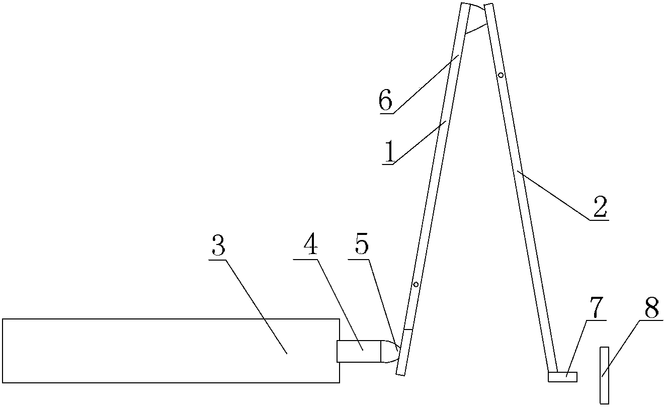
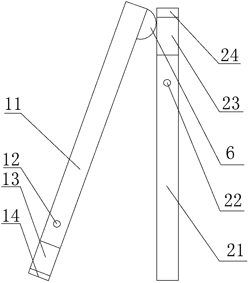
[0009] Specific implementation mode one: combine figure 1 and figure 2 Describe this embodiment, the described device of this embodiment comprises one-stage lever transmission device 1, two-stage lever transmission device 2, magnetostrictive rod 3, magnetic isolation plate 4, one-stage arc-shaped strong magnet 5, two-stage circle The arc-shaped strong magnet 6, the trigger head 7 and the trigger detector 8, the primary lever transmission device 1 is composed of a first lever, a first lever shaft 12 and a first ferromagnetic material layer 14, and the first lever includes a first long rod 11 And the first short rod 13, the outside of one end of the first short rod 13 is provided with a first ferromagnetic material layer 14, the other end of the first short rod 13 is connected with one end of the first long rod 11 and made into one, the first The side wall of the other end of the long rod 11 is connected with an end of the secondary arc-shaped strong magnet 6, the first lever ...
specific Embodiment approach 2
[0012] Specific implementation mode two: combination figure 1 Describe this embodiment, the magnetostrictive rod 3 of this embodiment is made of rare earth giant magnetostrictive material Tb 0.27 Dy 0.73 Fe 2 Made, the length of the magnetostrictive rod 3 is 180-220mm, and this structure is used to reduce interference. Other implementation manners are the same as the specific implementation manner 1.
specific Embodiment approach 3
[0013] Specific implementation mode three: combination figure 1 To describe this embodiment, the horizontal distance between the trigger detector 8 and the trigger head 7 of this embodiment is 30-40mm. Other implementation manners are the same as the specific implementation manner 1.
[0014] How it works: combined figure 1 and figure 2 Explain the working process of the present invention: when the wire passes through the current, the magnetostrictive rod 3 is placed in the magnetic field near the wire, and the magnetostrictive rod 3 performs telescopic movement under the action of the magnetic field to drive the magnetic isolation The plate 4 reciprocates, and the magnetic isolation plate 4 pushes the first-level arc-shaped strong magnet 5, and the first-level arc-shaped strong magnet 5 drives the first-level lever transmission device 1 to move by the magnetic adsorption force, so The primary lever transmission device 1 drives the secondary lever transmission device 2 to ...
PUM
 Abstract
Description
Claims
Application Information
 - R&D
- Intellectual Property
- Life Sciences
- Materials
- Tech Scout
- Unparalleled Data Quality
- Higher Quality Content
- 60% Fewer Hallucinations
Browse by: Latest US Patents, China's latest patents, Technical Efficacy Thesaurus, Application Domain, Technology Topic, Popular Technical Reports.
© 2025 PatSnap. All rights reserved.Legal|Privacy policy|Modern Slavery Act Transparency Statement|Sitemap|About US| Contact US: help@patsnap.com


