
Magnetostrictive open circuit optical control device

A technology of optical control and magnetostriction, applied in the direction of measuring devices, overcurrent protection, instruments, etc., can solve the problems of complex circuit structure, complex signal processing, rejection of action, etc., and achieve fast response and reliability High, the effect of introducing less error

Active Publication Date: 2015-03-11
HARBIN INST OF TECH
View PDF6 Cites 0 Cited by
  • Summary
  • Abstract
  • Description
  • Claims
  • Application Information

AI Technical Summary

Problems solved by technology

[0003] The purpose of the present invention is to provide a device for optical control of magnetostrictive circuit breaker in order to solve the problem of complex signal processing and complex circuit structure of existing magnetostrictive transformers, which are prone to misoperation or refusal to operate.

Method used


Image

  • Magnetostrictive open circuit optical control device

Examples


specific Embodiment approach 1

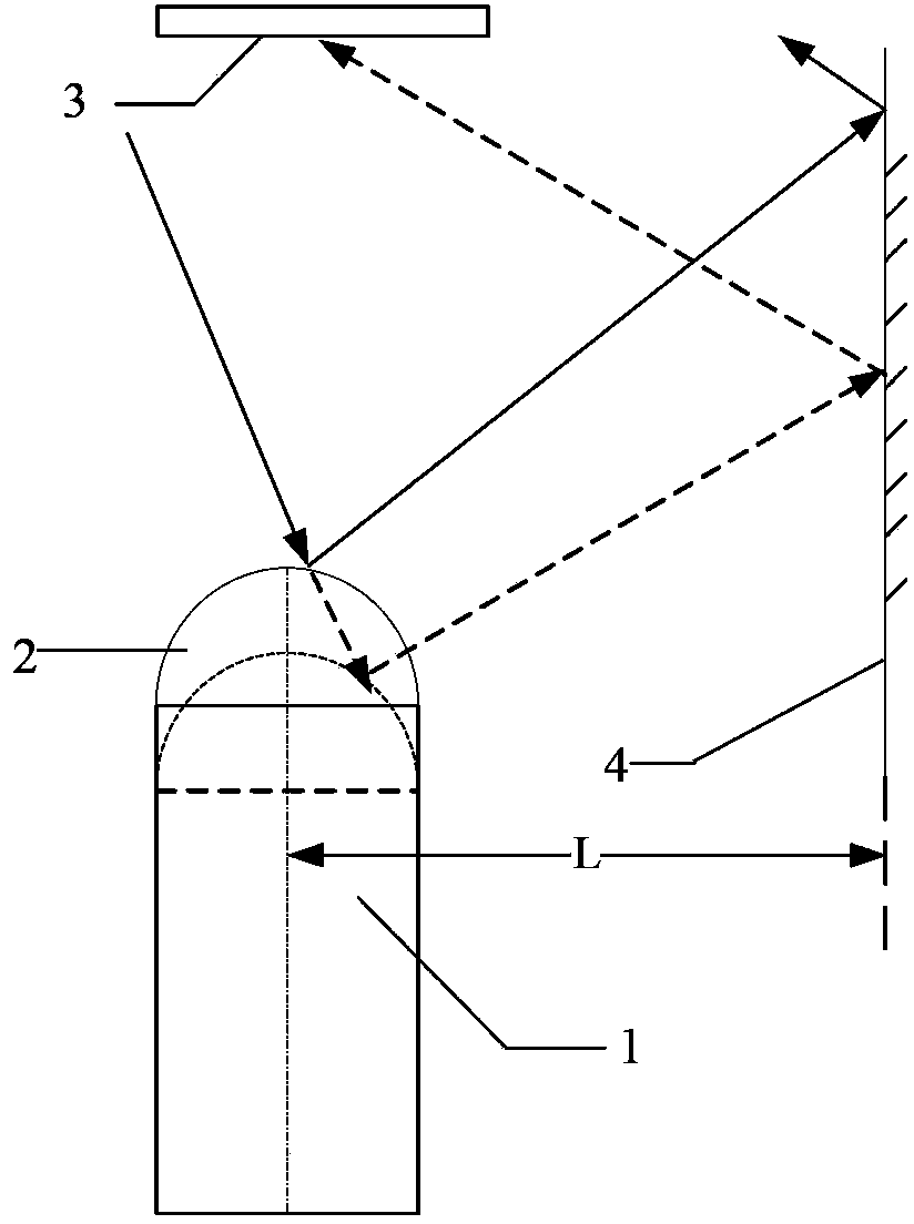
[0012] Specific implementation mode one: combine figure 1 Describe this embodiment, the device of magnetostrictive circuit breaker optical control described in this embodiment, it comprises the sensing head 1 of magnetostrictive material, sensing head spherical reflector 2, laser detector 3 and parallel reflector 4, The sensor head 1 of the magnetostrictive material is a cylinder, and the spherical reflector 2 of the sensor head is a hemisphere, and the sphere radius of the spherical reflector 2 of the sensor head is the same as that of the sensor head 1 of the magnetostrictive material. The radius of the end face circle is the same, the sensing head spherical reflector 2 is coaxially arranged with the sensing head 1 of the magnetostrictive material, and the bottom surface of the sensing head spherical reflector 2 is fixed on the bottom surface of the sensing head 1 of the magnetostrictive material. The upper end surface is connected with the sensor head 1 of the magnetostrict...

specific Embodiment approach 2

[0015] Specific embodiment two: the difference between this embodiment and the device for magnetostrictive circuit breaker optical control described in specific embodiment one is that it also includes a counter, the input end of the counter communicates with the electrical signal output end of the laser detector 3, The output terminal of the counter is the output terminal of the disconnection start signal of the device for magnetostrictive disconnection optical control.

[0016] Considering that there may be some non-faulty instantaneous currents that are too large during the operation of the power grid, the electrical signal output terminal of the laser detector 3 is connected to a counter, and a short-circuit signal is sent after N times of laser scanning times are detected, and N is an integer greater than 1; avoid Occurrence of malfunction.

specific Embodiment approach 3

[0017] Embodiment 3: This embodiment is a further limitation of the device for optical control of the magnetostrictive circuit breaker described in Embodiment 1. The sensor head 1 made of magnetostrictive material is realized by using a cylinder with a length of 200 mm.


PUM


Abstract

The invention provides a magnetostrictive open circuit optical control device, and relates to the field of magnetostrictive effect optical current transformers. Problems that the conventional magnetostrictive transformer is complex in signal processing and circuit structure, and false operation or refusal operation is caused easily are solved. The magnetostrictive open circuit optical control device comprises a sensing head made of a magnetostrictive material, a sensing head spherical reflector, a laser detector and a parallel reflector, wherein the bottom surface of the sensing head spherical reflector is fixed on the upper end surface of the sensing head made of the magnetostrictive material and is connected with the sensing head made of the magnetostrictive material to form a whole; the laser detector is arranged over the sensing head spherical reflector; the parallel reflector is arranged in a light path between the reflecting light of the sensing head spherical reflector and the incident light of the laser detector; the distance between the parallel reflector and the axle center of the sensing head made of the magnetostrictive material is L; and an electric signal output end of the laser detector is an open circuit starting signal output end of the magnetostrictive open circuit optical control device. The magnetostrictive open circuit optical control device is applicable to the field of magnetostrictive effect optical current transformers.

Description

technical field [0001] The invention relates to the field of magnetostrictive effect optical current transformers. Background technique [0002] The current transformer protection part design based on the principle of magnetostriction is that when the bus bar is short-circuited, the current flowing through it will become larger than the normal value, and the mechanical deformation generated by the rare earth giant magnetostrictive material will be converted into electrical current after measurement. The signal, the electrical signal is transmitted to the control circuit for analysis, and the circuit breaker signal is generated when the short circuit is confirmed. Finally, the electrical signal acts on the circuit breaker to open the circuit. In this process, the processing of the signal is relatively complicated, and some errors are easy to cause misoperation or rejection. action, and the required circuit structure is also very complex. Contents of the invention [0003] ...

Claims


Application Information

Patent Timeline
Patent Type & Authority Patents(China)
IPC IPC(8): G01R19/00H02H3/08
Inventor 申岩郭志忠张国庆于文斌陆忠峰程嵩
Owner HARBIN INST OF TECH
Learn More