Eureka AIR delivers breakthrough ideas for toughest innovation challenges, trusted by R&D personnel around the world.

Sector-shaped spraying generating device

A technology of generating device and fan shape, applied in the direction of spraying device, spraying device, etc., can solve the problems of small cleaning force, no water saving effect, and inability to form a suction effect, etc., to achieve strong spraying force, good water saving effect, particle delicate effect

Inactive Publication Date: 2012-11-21
XIAMEN SOLEX HIGH TECH IND CO LTD +1
View PDF5 Cites 0 Cited by
  • Summary
  • Abstract
  • Description
  • Claims
  • Application Information

AI Technical Summary

Problems solved by technology

[0003] Traditional fan-shaped spraying often needs to pressurize and reshape the liquid flow to achieve fan-shaped spraying water, so it is not suitable for liquids working under normal pressure; on the other hand, the traditional method is only for liquid flow. It is only processed by the shape of the machine, and it cannot form an air suction effect, its cleaning power is small, and it does not have a water-saving effect

Method used


Image

  • Sector-shaped spraying generating device
  • Sector-shaped spraying generating device
  • Sector-shaped spraying generating device

Examples


Embodiment 1

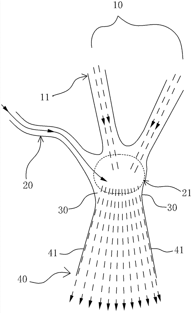
[0028] Such as figure 1 Shown is a schematic diagram of an embodiment of the invention with liquid and air flow. There are two water inlet passages 11, which have obvious angles between each other. The two water inlet passages 11 converge in the intersection area 21 shown by the closed dotted line; the intersection area 21 is also connected to an air suction channel 20, and the air suction channel 20 The inlet is exposed to the air in free space and has a pressure of one atmosphere.

[0029] The dotted arrows indicate the direction of water flow, and the solid arrows indicate the direction of air flow.

[0030] Downstream of the converging area 21 is a flat spout 40 , the flat spout 40 has a substantially uniform thickness in the direction perpendicular to the paper, and is much smaller than the distance between the shaping walls 41 , and is flat. The flat nozzle 40 has a throat 30 near the confluence region 21 . The cross-sectional area where the throat 30 is located is sl...

Embodiment 2

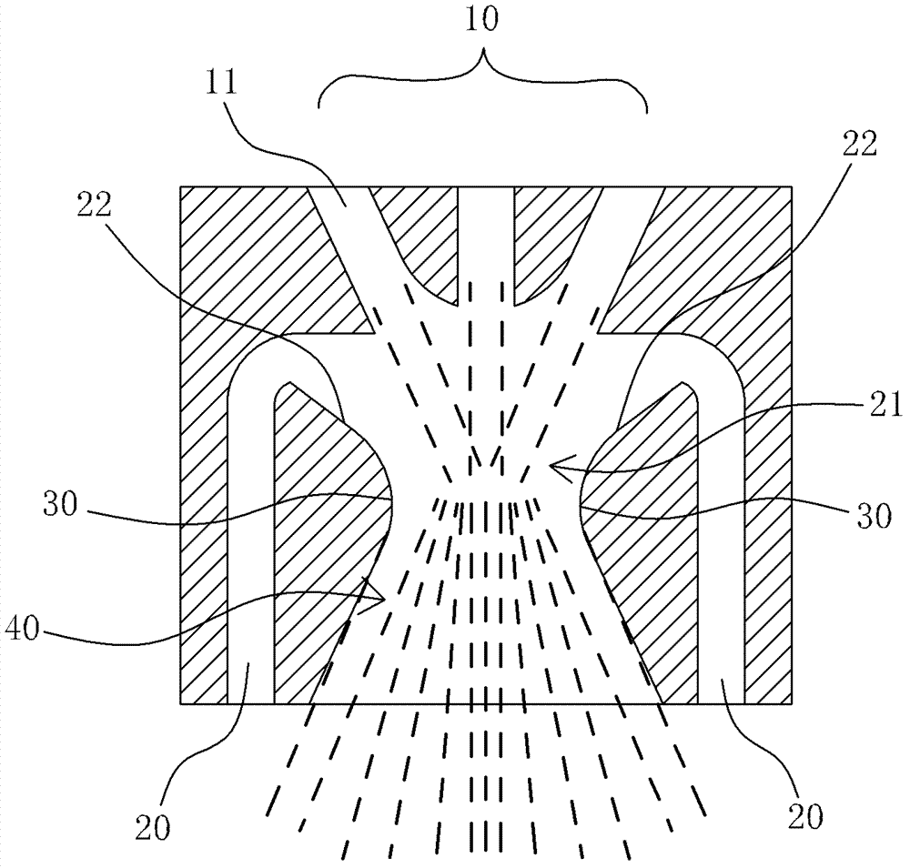
[0033] Such as figure 2 Shown is a schematic diagram of Embodiment 2 of the present invention. In this embodiment, the water inlet 10 , the suction channel 20 , the throat 30 , and the flat nozzle 40 are all left-right symmetrical, and have the same depth in the direction perpendicular to the paper. The water inlet 10 has three water inlet channels 11 . The air suction channel 20 has an inclined surface 22 near the confluence region 21 towards the flat nozzle 40 . This inclined surface makes it difficult for the air bubbles to block the air suction channel 20 , so that it can be sprayed out from the flat nozzle 40 smoothly.

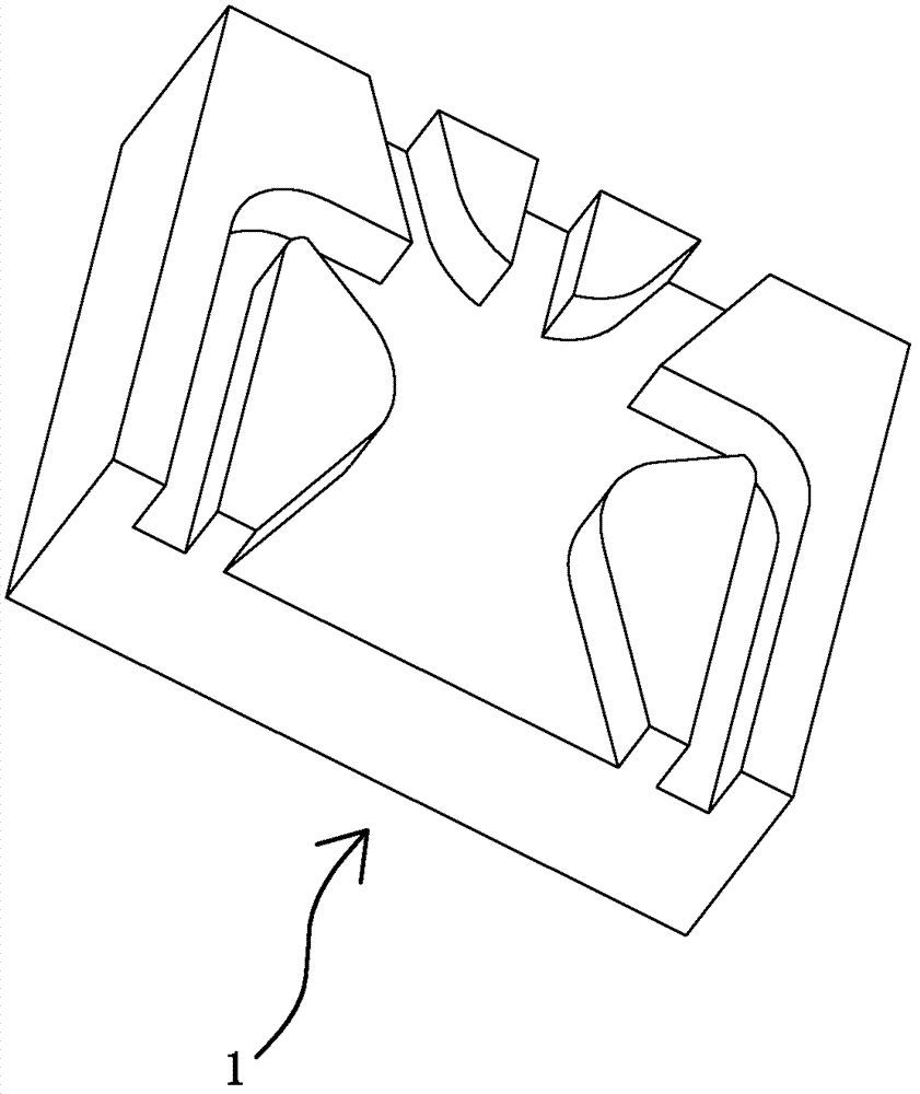
[0034] image 3 yes figure 2 Example product perspective view. All waterways are formed on a rectangular face of a mosaic 1 with the same depth. The inlay 1 is inlaid and fixed on the required equipment, thus constituting a modular accessory; combining figure 2 It can be seen that the suction channel 20 and the outlet of the flat nozzle 40 are on...


PUM


Abstract

The invention discloses a sector-shaped spraying generating device, which comprises a complete water path from water intake to water outtake and is characterized by comprising a water inlet, an air sucking channel and a flat nozzle, wherein the water inlet comprises at least two water inlet channels; all water inlet channels are gathered at a joining area; at least one air sucking channel which is communicated with the joining area from an outer free space is provided; the flat nozzle is arranged at a downstream water path at the joining area and is provided with a throat with which water flow can be formed into liquid sealing; the area of the cross section of the throat is 1 to 3 times of the maximum total area of the cross section of the water inlet; and the flat nozzle has a shaping wall which becomes larger gradually from the throat to outside gradually. According to the sector-shaped spraying generating device in such form, a mode that the water inlet channel is gathered and combined with the air sucking channel is adopted, and then the water flow in a sector-shape can be formed without high water pressure; and meanwhile as the device has the air sucking effect, the water is sprayed in the sector-shape with fine grains, strong spraying force, good cleaning force and good water conservation effect, so that the device can be applied in various situations.

Description

technical field [0001] The invention relates to a liquid distributing part, in particular to a generating device for fan-shaped spraying. Background technique [0002] Transforming liquid into a fan-shaped spray has applications in many fields, such as showering, cleaning, watering and so on. Because the liquid usually has a small cross-sectional area when it is conveyed, if it is to be adjusted to spread out in a fan shape, specific mechanical components must be required to handle the liquid flow. [0003] Traditional fan-shaped spraying often needs to pressurize and reshape the liquid flow to achieve fan-shaped spraying water, so it is not suitable for liquids working under normal pressure; on the other hand, the traditional method is only for liquid flow. It is only processed in the shape of the machine, and it cannot form an air suction effect, its cleaning power is small, and it does not have a water-saving effect. [0004] Therefore, there is a demand, that is, how t...

Claims


Application Information

Patent Timeline
IPC IPC(8): B05B1/04
Inventor 冀洋锋李清双曹斌周华松
Owner XIAMEN SOLEX HIGH TECH IND CO LTD
Why Eureka
Eureka Blog
Learn More