
Pneumatic floating-supporting device

A floating support and pneumatic technology, applied in positioning device, support, clamping and other directions, can solve the problems of elastic deformation, spring knife, fixed support column support height cannot be adjusted, etc., to achieve the effect of preventing deformation and simple structure

Inactive Publication Date: 2012-11-21
CHONGQING BAIJI SIXING DIE CASTING
View PDF7 Cites 11 Cited by
  • Summary
  • Abstract
  • Description
  • Claims
  • Application Information

AI Technical Summary

Problems solved by technology

[0002] Thin-walled parts are very sensitive to various influencing factors during processing, and are easily deformed. It is difficult to meet the accuracy requirements and seriously affect product quality. Therefore, it has become a major problem in mechanical processing.
At present, three-point clamping is usually used for clamping and positioning of thin-walled parts. The parts far from the clamping point will have elastic deformation during punching or other types of processing, resulting in poor product flatness, knife snapping, or Problems such as aperture out of round
[0003] Patent 201120151749.8 discloses a support device for processing thin-walled sleeves, which provides inner diameter support for thin-walled sleeves and prevents deformation of thin-walled sleeves during processing, but this support device is not suitable for thin-walled or other thin-walled sleeves. Thin wall, small scope of application
[0004] In the clamping process of the existing sheet-shaped thin-walled parts, the support is usually provided by a fixed support column. The disadvantage is that the support height of this fixed support column cannot be adjusted, and it cannot meet the support requirements of most thin-walled parts.

Method used


Image

  • Pneumatic floating-supporting device

Examples


Embodiment Construction

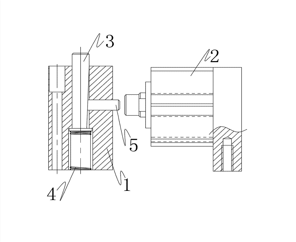
[0012] refer to figure 1 , a pneumatic floating support device, comprising a support sleeve 1 mounted on a workpiece tooling through bolts, and a locking cylinder 2 is arranged adjacent to the support sleeve 1 .

[0013] The support sleeve 1 is provided with a floating support column 3 aligned with the supporting part of the thin-walled part. The upper end of the floating support column 3 protrudes from the support sleeve 1, and the lower end of the floating support column 3 is provided with a spring 4. The floating support column 3 can be placed on the support sleeve. 1 reciprocates up and down; the side of the support sleeve 1 is provided with a pin hole, and a locking pin 5 that can be pressed against the floating support column 3 is interspersed in the pin hole, and the contact surface between the locking pin 5 and the floating support column 3 is an inclined plane ; The locking pin 5 is set opposite to the output shaft of the locking cylinder 2, and the output shaft of th...


PUM


Abstract

The invention discloses a pneumatic floating-supporting device, which comprises a supporting sleeve, wherein the supporting sleeve is installed on workpiece equipment, and a locking cylinder is arranged beside the supporting sleeve; a floating-supporting column which is aligned with a thin-wall part-supporting part is arranged in the supporting sleeve, and the lower end of the floating-supporting column is provided with a spring; and the lateral surface of the supporting sleeve is provided with a pin hole, a locking pin which can be tightly abutted against the floating-supporting column is inserted into the pin hole in a penetrating way, and the locking pin and an output shaft of the locking cylinder are oppositely arranged. The pneumatic floating-supporting device has a simple structure and can be used for providing supporting for other parts except for barrel-shaped thin-wall parts to prevent the thin-wall parts from being deformed in processing.

Description

technical field [0001] The invention discloses a fixture accessory, in particular to a pneumatic floating support device. Background technique [0002] Thin-walled parts are very sensitive to various influencing factors during processing, easily deformed, difficult to meet precision requirements, and seriously affect product quality, thus becoming a major problem in mechanical processing. At present, three-point clamping is usually used for clamping and positioning of thin-walled parts. The parts far from the clamping point will be elastically deformed during punching or other types of processing, resulting in poor product flatness, knife snapping, or Aperture out of round and so on. [0003] Patent 201120151749.8 discloses a support device for processing thin-walled sleeves, which provides inner diameter support for thin-walled sleeves and prevents deformation of thin-walled sleeves during processing, but this support device is not suitable for thin-walled flakes or other ...

Claims


Application Information

Patent Timeline
IPC IPC(8): B23Q3/00
Inventor 左麟曹彦
Owner CHONGQING BAIJI SIXING DIE CASTING
Learn More