Amphibious robot with deformable foot-web compounded propulsion mechanism

A technology of amphibious and propulsion mechanism, which is applied to amphibious vehicles, motor vehicles, transportation and packaging, etc. It can solve the problems of poor passing capacity and low efficiency, and achieve the effect of easy maintenance and replacement, flexible movement mode and stable stability

Inactive Publication Date: 2012-11-21
UNIV OF SCI & TECH OF CHINA
3 Cites 41 Cited by

AI-Extracted Technical Summary

Problems solved by technology

[0003] The purpose of the present invention is to provide an amphibious robot based on a deformable foot-web composite propulsion mechanism, which solves the problem that most of the existing amphibious robots need two sets of inde...

Abstract

The invention relates to an amphibious robot with a deformable foot-web compounded propulsion mechanism, which comprises a sealed housing of the amphibious robot, a sealed cover plate, a front cover plate, a rear cover plate, a control circuit, a battery, a communication antenna, a plurality of compounded propulsion driver modules and a plurality of deformable foot-web modules, wherein the compounded propulsion driver modules are arranged on two side plates of the sealed housing symmetrically; and a deformable foot-web module is mounted on the output shaft of each compounded propulsion driver module. According to the invention, the problems that most of the conventional amphibious robots requires two sets of independent land and water propulsion mechanisms, and the trafficability and the efficiency of the conventional amphibious robots are poor in a complex amphibious transitional environment are solved, so as to provide an efficient high-tech means for exploitation and utilization of offshore marine resources, amphibious expedition and rescue.

Application Domain

Technology Topic

Image

  • Amphibious robot with deformable foot-web compounded propulsion mechanism
  • Amphibious robot with deformable foot-web compounded propulsion mechanism
  • Amphibious robot with deformable foot-web compounded propulsion mechanism

Examples

  • Experimental program(1)

Example Embodiment

[0027] The present invention will be described in further detail below in conjunction with the accompanying drawings.
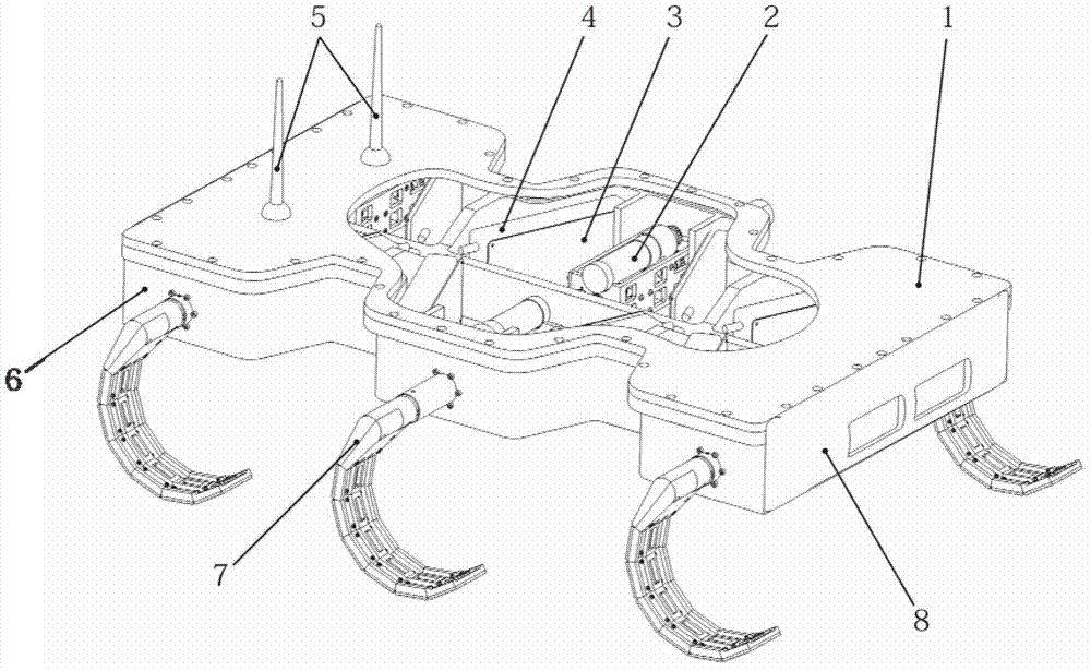
[0028] like figure 1 As shown, the robot of the present invention includes a sealing cover plate 1, a composite propulsion driving module 2, a control circuit 3, a battery 4, a communication antenna 5, a sealing shell 6, a deformable foot-fin module 7, and a front/rear cover plate 8, The joint surface between the sealing cover plate 1 and the sealing shell 6 is sealed by a sealing strip and a sealant and then connected by screws, and the front/rear cover plates 8 are respectively bonded to the front and rear sides of the sealing shell 6, The control circuit 3 and the battery 4 are fixed in the sealed casing 6 by screws, the communication antenna 5 is fixed on the sealed cover 1, and its signal transmission cable is connected with the control circuit 3; There are multiple composite propulsion driving modules 2 , and the output shaft end of each composite propulsion driving module 2 is connected with a deformable foot-webbed module 7 . The composite propulsion drive modules 2 in this embodiment have three pairs or six, which are symmetrically distributed in the front, middle and rear of the sealed housing 6. The three pairs and six deformable foot-web modules 7 are respectively fixed by tightening screws. Connected to the output shaft end of each composite propulsion drive module 2 .
[0029] like figure 2 As shown, the deformable foot-web module 7 includes a first base plate 16, a first cover plate 9, a plurality of middle sections 10, a distal section 11, an elastic sheet 15, a non-stretchable cord 14, and a non-stretchable cord pressing piece 12. and non-stretchable cord grips 13. In this embodiment, there are five middle sections. The base plate 16 of the first section, the five middle sections 10 and the last section 11 are fixed on the elastic thin plate 15 by screws in sequence, and the non-stretchable soft rope 14 passes through the base plate 16 of the first section, the through holes on the five middle sections 10 and the last section 11 are folded back and assembled together. It is clamped by the non-stretchable cord clamp 13 and pressed with the non-stretchable cord pressing piece 12 to prevent it from falling off. The cover plate 9 of the first section and the base plate 16 of the first section are fixedly connected by screws. figure 2 In order for the deformable foot-webbed module 7 to become an underwater driving mechanism similar to webbed in the state of non-stretchable soft rope relaxation, image 3 For the deformable foot-web module 7 becomes a foot-like land drive mechanism in the unstretchable cord-tightened state.
[0030] like Figure 4 and Figure 5As shown, the composite propulsion drive module 2 includes a main drive motor 17, a drive module frame cover 18, a drive module frame 19, a zero position detection plate 20, a slot-shaped photoelectric switch 21, a main drive motor bracket 22, a bearing seat 23, and a wire take-up Motor 24, nut sleeve 25, second take-up gear 26, first take-up gear 27, first drive gear 28, second drive gear 29, O-ring 30, seal cavity screw 31, transmission hollow shaft first Bearing 32, sealed cavity bearing end cover 33, transmission hollow shaft 34, shaft retaining ring 35, non-retractable soft rope connecting block 36, first connecting rod 37, transmission hollow shaft second bearing 38, connecting pin 39, first Connecting rod bearing 40, second connecting rod 41, second connecting rod bearing 42, screw first bearing 43, linear bearing 44, nut 45, optical axis 46, sleeve end cover 47, screw 48, screw second Bearing 49, screw bearing end cover 50. The main drive motor 17 is a commercially available product, purchased from Suzhou Junhe Servo Technology Co., Ltd. (manufacturer: Maxon Company of Switzerland), the model is Maxon RE 30, and is fixed on the main drive motor bracket 22 by screws. The transmission hollow shaft 34 is supported by the first bearing 32 of the transmission hollow shaft and the second bearing 38 of the transmission hollow shaft, and is installed on the drive module frame 19 and the main drive motor bracket 22, and the drive module frame 19 and the main drive motor bracket 22 are fixed by screws. one. The output shaft of the main drive motor 17 is connected to the first drive gear 28 through a set screw, and the second drive gear 29 meshing with the first drive gear 28 is fixed on the transmission hollow shaft 34 through a flat key and a shaft retaining ring 35 . A through hole with a diameter of about 1.5 mm is opened on the central axis of the transmission hollow shaft 34, and the non-stretchable soft rope 14 can slide in the through hole. After the wire take-up motor 24 is driven by the first wire take-up gear 27 and the second wire take-up gear 26, it drives the screw rod 48 to rotate, and the screw rod 48 and the nut 45 form a screw drive so that the nut sleeve 25 fixed on the nut 45 can be driven. A linear displacement is generated in the axial direction of the transmission hollow shaft 34, thereby passing through the first connecting rod bearing 40, the second connecting rod bearing 42, the second connecting rod 41, the first connecting rod 37 and the non-stretching soft rope connecting block 36. A series of transmissions cause the non-stretching cord 14 to produce a synchronous linear displacement. Linear bearing 44 and optical axis 46 are used to guide the linear movement of nut sleeve 25 and prevent it from rotating. The transmission hollow shaft 34 is fixedly connected to the zero position detection plate 20 by means of tightening screws, and cooperates with the slot-shaped photoelectric switch 21 fixed on the drive module frame 19 to detect the rotation zero position. The protruding end of the drive module frame 19 and the transmission hollow shaft 34 form a cavity, and a viscous sealant is filled through the small hole at the sealing cavity screw 31 for sealing and waterproofing. The driving module frame 19 is sealed and waterproof with the amphibious robot sealing shell 6 through the O-ring 30 .
[0031] The amphibious robot of the present invention can realize two movement modes of land foot type movement and water webbed type swimming in the amphibious environment.
[0032] Land-footed motion mode: when the deformable foot-webbed module 7 performs a rotary motion under the drive of the transmission hollow shaft 34, the functions of the amphibious robot such as walking on land and climbing over obstacles can be realized. Supplemented by different control sequences, changes in the walking gait of the amphibious robot can be realized. like Figure 6a As shown, when the amphibious robot walks on a relatively flat ground, the triangular gait propulsion method in the figure can be adopted, that is, the six sets of deformable foot-web modules 7 are divided into two groups, and each group consists of three sets of deformable feet distributed in a triangle. -The web module is composed of 7, and there is a certain driving timing phase difference between the two groups, so as to ensure the stability and rapidity of the robot as a whole during the traveling process. like Figure 6b As shown, when the amphibious robot needs to climb over obstacles of a certain height, the synchronous gait propulsion method in the figure can be adopted, that is, the six sets of deformable foot-fin modules 7 are divided into three groups, respectively consisting of two opposite front, middle and rear. It is composed of a set of modules, and there is a certain drive timing phase difference between each group, so as to realize the passability and coordination of the robot as a whole in the process of overcoming obstacles.
[0033] Water fin swimming mode: such as Figure 7a As shown, when the deformable foot-web module 7 makes a small-scale flapping motion near the plane parallel to the body of the robot, the robot can achieve positive swimming; as in Figure 7b shown, when the deformable foot-web module 7 is in Figure 7a When the indicated position is rotated 180° and then flaps, the robot can swim in the opposite direction; for example Figure 7c As shown in the figure, when the deformable foot-webbed module 7 on one side of the robot makes a flapping motion, the robot can turn left or right to swim; for example Figure 7d As shown in the figure, when the deformable foot-fin modules 7 on both sides of the robot body are dislocated by 180° to perform the flapping motion, the robot can realize the underwater spin swimming in place; such as Figure 7e As shown in the figure, when the deformable foot-web module 7 is located at a position perpendicular to the plane of the robot body, the emergency braking action of the robot under water can be realized; such as Figure 7f and Figure 7g As shown, when the deformable foot-webbed module 7 performs a flapping motion at a position that forms a certain angle with the plane of the robot body, the robot can achieve floating or diving swimming motion.

PUM

no PUM

Description & Claims & Application Information

We can also present the details of the Description, Claims and Application information to help users get a comprehensive understanding of the technical details of the patent, such as background art, summary of invention, brief description of drawings, description of embodiments, and other original content. On the other hand, users can also determine the specific scope of protection of the technology through the list of claims; as well as understand the changes in the life cycle of the technology with the presentation of the patent timeline. Login to view more.

Similar technology patents

Classification and recommendation of technical efficacy words

  • Easy maintenance and replacement
  • Guaranteed stability

Preparation method of metal-organic framework compound with hierarchical pore structure

InactiveCN104151336AGuaranteed stabilityMaintain crystal shapeCopper organic compoundsZinc organic compoundsSolventIon
Owner:FUDAN UNIV
Why Eureka
Try Eureka