
Heating unit for vehicle heating

A heating device and heating unit technology, applied in vehicle components, heating/cooling equipment, transportation and packaging, etc., can solve the problems of shorter charging cycle, shorter vehicle travel distance, and more power consumption

Active Publication Date: 2016-08-17
吉尼克斯株式会社
View PDF9 Cites 0 Cited by
  • Summary
  • Abstract
  • Description
  • Claims
  • Application Information

AI Technical Summary

Problems solved by technology

[0008] The problem to be solved is that the vehicle's air conditioner, especially heating, consumes a lot of power, the vehicle's driving distance is shortened, and the charging cycle is shortened.

Method used


Image

  • Heating unit for vehicle heating
  • Heating unit for vehicle heating
  • Heating unit for vehicle heating

Examples


Embodiment 1

[0020] Hereinafter, the present invention will be described with reference to diagrams showing embodiments in which the vehicle heating apparatus of the present invention is arranged in an air-conditioning unit.

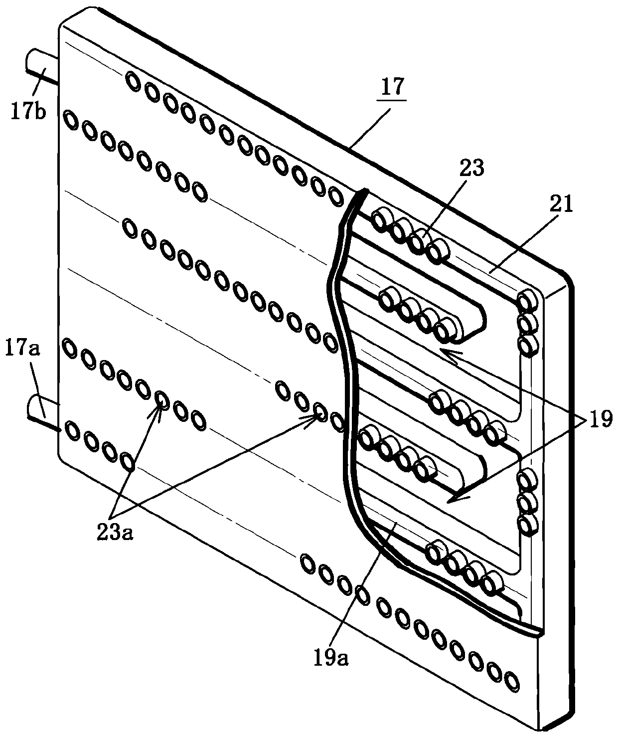
[0021] Figure 1 to Figure 3 An example of a vehicle air conditioner for a hybrid vehicle is shown. The air conditioner 1 constituting the vehicle air conditioner is arranged below the instrument panel in the vehicle, and is rotated by a blower fan (not shown) through the inside and outside air switching door. On the other hand, the blown air (including mixed air of the inside air and the outside air) of at least one of the sucked inside air and outside air is blown into the air conditioning unit 1 through the air inlet 3 . The air blown to the air conditioning unit 1 passes through the evaporator and is cooled, and then passes or is bypassed by the heating unit 7 of the vehicle heater at a ratio corresponding to the opening degree of the air mix door to generate a p...

Embodiment 2

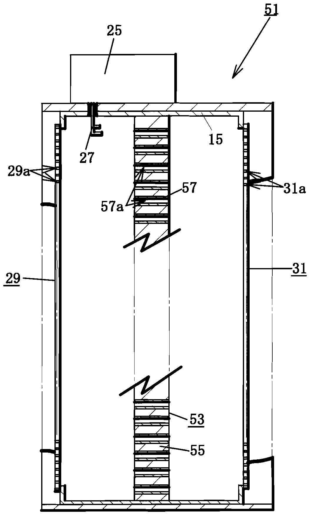
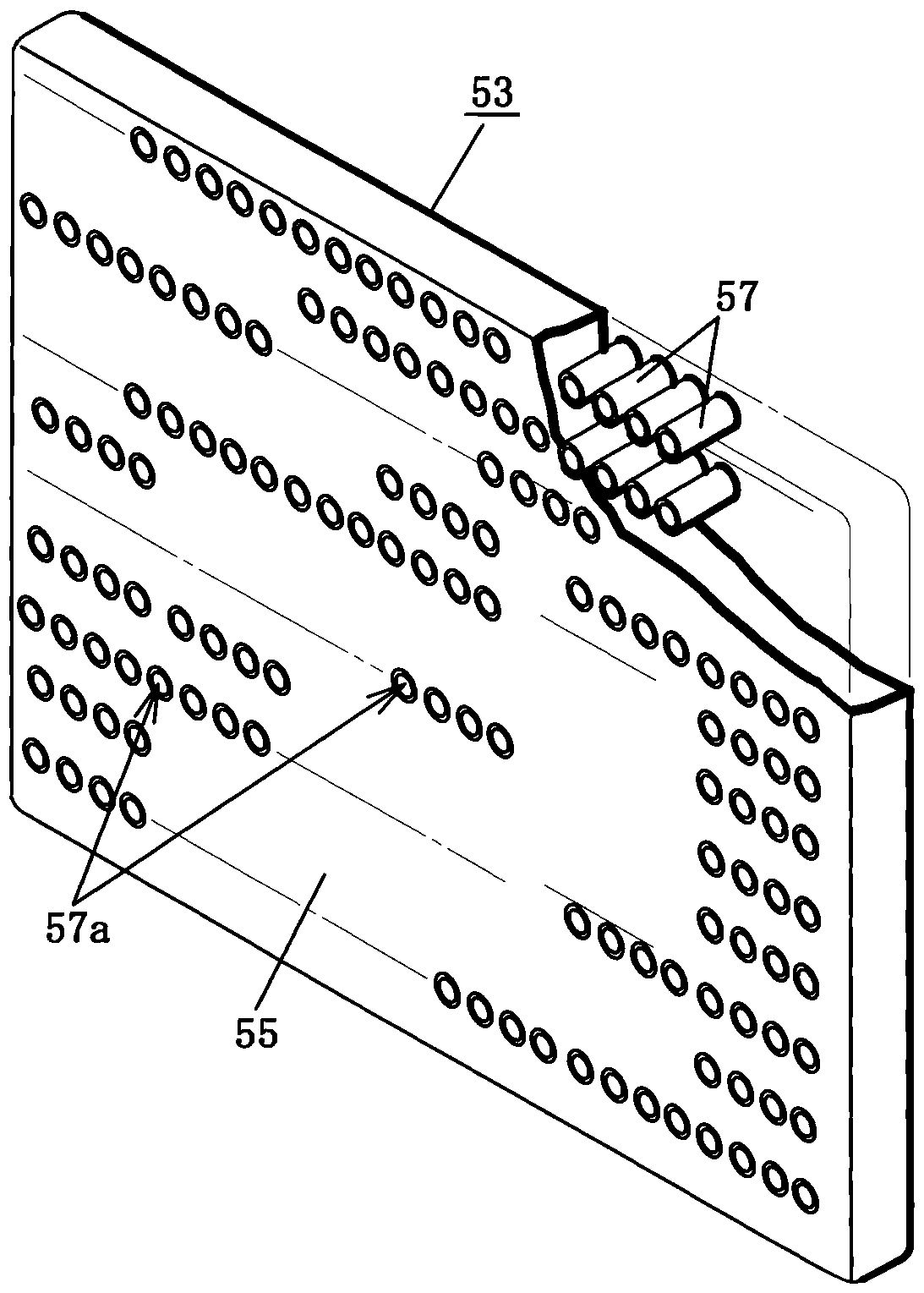
[0042] Figure 5 and Image 6 An example of a vehicle air conditioner for an electric vehicle or a hybrid vehicle equipped with an air-cooled engine is shown. Except for the point that the heater core 53 of the heating unit 51 is configured as follows, other configurations are due to and implemented. Since it is the same as Example 1, the same symbols are attached and detailed descriptions are omitted.

[0043] In the frame body 15 of the heating unit 51 , a heater core 53 is arranged so as to be perpendicular to the air blowing direction at an intermediate portion in the air blowing direction. The carrier 55 of the heater core 53 is formed of a magnetically permeable ceramic, a heat-resistant synthetic resin material, or the like in a plate shape of a size capable of closing the space portion of the frame body 15 . A large number of microwave absorbing heating elements 57 having an axis in the air blowing direction and a hollow portion 57a ​​in the center are provided at pr...


PUM


Abstract

The invention relates to a heating unit of an automobile heat supply device, which is used to reduce the power consumed for heat supply of the automobile, prolong the operating range and prolong the recharging period of the automobile. The heating unit comprises a frame body, support carriers, microwave absorbing heating bodies and a microwave output unit, wherein the frame body is arranged inside an air supply flow path, is provided with a hollow part through which the supplied air can flow, and is composed of openings and metal materials; wherein the supplied air can flow out or flow into the weather side or the leeward of the openings in the air supply direction; the metal materials have the function of shielding microwaves in an electromagnetic mode; the support carriers are arranged inside the hollow part of the frame body; a plurality of microwave absorbing heating bodies are arranged at proper intervals relative to the support carriers; the microwave absorbing heating bodies are provided with hollow parts, wherein the two end parts of the hollow parts at the weather side or a leeward in the air supply direction are opened; the microwave output unit is arranged inside the frame body and is used for outputting microwaves towards each microwave absorbing heating body.

Description

technical field [0001] The present invention relates to a heating unit of a heating device for a vehicle, and relates in detail to a heating unit in which a microwave-absorbing heat-generating body is provided in a vehicle air-conditioning unit or a vehicle air duct to heat the blown air with low power consumption. Background technique [0002] In recent years, in order to improve the fuel efficiency of vehicles and reduce CO 2 Gas emissions, proposed to develop various hybrid vehicles, electric vehicles. Among these vehicles, electric vehicles in particular have the problem of significant power consumption and shortened cruising distance because the motor is driven by electric power from a mounted battery (storage battery) when the vehicle is driven by the motor. Therefore, although the cruising distance can be increased by increasing the installed battery capacity, the weight of the vehicle is increased, the power consumption efficiency is lowered, the travelable distance...

Claims


Application Information

Patent Timeline
Patent Type & Authority Patents(China)
IPC IPC(8): B60H1/22
Inventor 丹羽则夫野田了诚安斎弘树
Owner 吉尼克斯株式会社
Learn More