Method and device for manufacturing rocking arm with main piston and auxiliary piston

A technology of braking device and main piston, applied in valve device, engine components, engine control and other directions, can solve the problems of poor reliability and durability, increased engine height and weight, inconvenient installation and debugging, etc.

Inactive Publication Date: 2012-11-21
SHANGHAI UNIVERSOON AUTOPARTS CO LTD
View PDF13 Cites 33 Cited by
  • Summary
  • Abstract
  • Description
  • Claims
  • Application Information

AI Technical Summary

Problems solved by technology

[0013] The object of the present invention is to provide a rocker arm braking method with main and auxiliary pistons, the rocker arm braking method with main and auxiliary pistons will solve the rel

Method used


Image

  • Method and device for manufacturing rocking arm with main piston and auxiliary piston
  • Method and device for manufacturing rocking arm with main piston and auxiliary piston
  • Method and device for manufacturing rocking arm with main piston and auxiliary piston

Examples


Embodiment 1

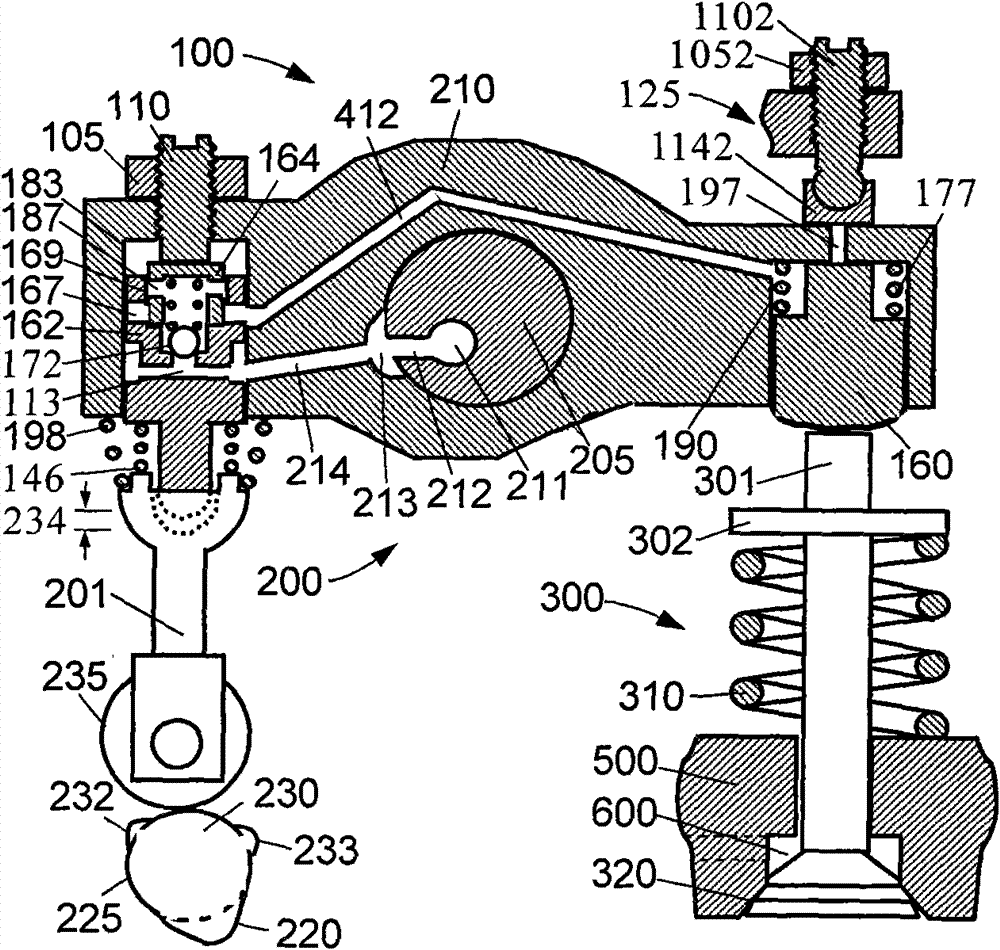
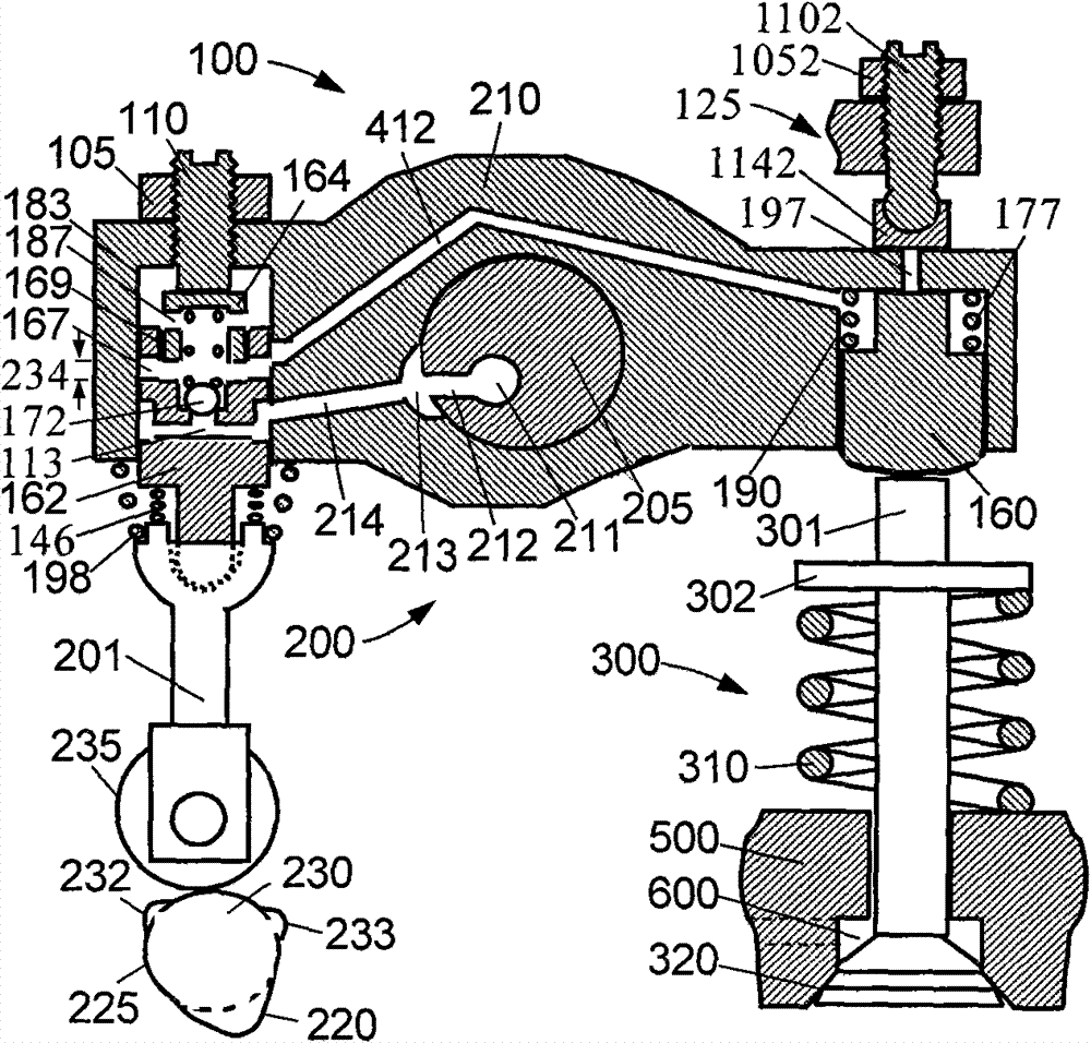
[0066] figure 1 and figure 2 Respectively represent the first embodiment of the rocker arm braking device with primary and secondary pistons of the present invention when the cam 230 is at the position of the inner base circle 225 during non-braking and braking. figure 1 and figure 2 It includes three main components: an exhaust valve actuator 200 , an exhaust valve mechanism 300 and an engine brake drive mechanism 100 .

[0067] The exhaust valve 301 of the exhaust valve mechanism 300 (only one exhaust valve is shown here, which may be multiple valves) is pushed on the valve seat 320 in the engine block 500 by the valve spring 310, preventing the gas (engine braking) air) between the engine cylinders and the exhaust pipe 600.

[0068] Exhaust valve actuator 200 includes cam 230 , cam follower 235 , pushrod 201 and rocker arm 210 . The exhaust valve actuator 200 and the exhaust valve 300 mechanism are collectively referred to as an exhaust valve drive chain. The end of ...

Embodiment 2

[0089] Figure 9 and Figure 10 Respectively represent the second embodiment of the rocker arm braking device with primary and secondary pistons of the present invention when the cam is in the position of the inner base circle during non-braking and braking. The difference between this embodiment and the first embodiment is that there is no switching piston installed above the primary piston 162 in this embodiment, and the hydraulic transmission between the primary piston hole 183 and the secondary piston hole 190 is always kept open. Therefore, during engine braking, most of the braking load on the secondary piston 160 is transmitted to the primary piston 162 , and only a small portion is transmitted to the brake bracket 125 above the rocker arm 210 .

[0090] The working principle and process of this embodiment are similar to those of the first embodiment, and will not be repeated here.


PUM


Abstract

Provided are a method and a device for manufacturing a rocking arm with a main piston and an auxiliary piston. A main piston hole and an auxiliary piston hole which are connected through a hydraulic channel are arranged in the rocking arm, the main piston is driven by using a braking boss on a cam, and the auxiliary piston is driven through hydraulic transmission to open at least one exhaust valve to achieve braking. During a braking process, an isometry section of a maximum braking lift of the braking cam is used, a retraction position of the main piston is kept, a hydraulic channel between the main piston hole and the auxiliary piston hole is closed, and a braking load on the auxiliary piston is transmitted to a braking support above the rocking arm. The main piston is further driven by an integrated exhaust boss on the cam, the main piston drives the rocking arm to move and be separated from the braking support, an oil discharging channel in the rocking arm is opened to discharge oil, the auxiliary piston is returned to the retraction position, and the exhaust valve is braked to move to a closed position. A compression releasing braking mechanism is integrated with the existing valve driving chain, braking load is borne by using the braking support, braking valve rise is reset, the braking load is reduced, and braking power is increased.

Description

Technical field: [0001] The invention relates to the mechanical field, in particular to the valve driving field of a vehicle engine, in particular to a rocker braking method and device with primary and secondary pistons. Background technique: [0002] In the prior art, engine braking technology is widely known. Engine braking is achieved by temporarily switching the engine to a compressor. The fuel is cut off during the conversion process, and the exhaust valve is opened at the end of the engine piston compression stroke to allow the compressed gas (air during braking) to be released. The energy absorbed by the engine during the compression stroke cannot be used in subsequent expansion. The stroke returns to the engine pistons, but is dissipated through the engine's exhaust and cooling system. The end result is effective engine braking that slows the vehicle. [0003] One precedent for an engine braking device is the hydraulic engine brake disclosed in US Patent No. 3,220...

Claims


Application Information

Patent Timeline
IPC IPC(8): F01L13/06F02D13/04F01L1/20
Inventor 杨洲
Owner SHANGHAI UNIVERSOON AUTOPARTS CO LTD
Why Eureka
Try Eureka