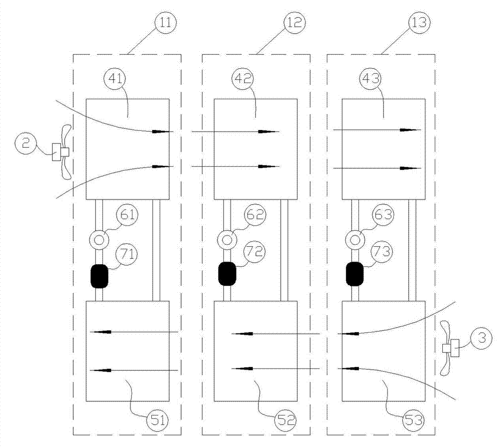
Multistage power heat pipe system
A technology of power heat pipe and heat exchanger, which is applied in the field of heat exchange, can solve the problems of large heat exchange temperature difference loss and low total heat exchange efficiency, and achieve the effects of reducing heat exchange temperature difference loss, improving heat exchange efficiency, and simple structure
Inactive Publication Date: 2012-11-21
BEIJING FULLLINK OREITH TECH CO LTD
View PDF9 Cites 1 Cited by
- Summary
- Abstract
- Description
- Claims
- Application Information
AI Technical Summary
Problems solved by technology
[0012] A new type of heat pipe heat exchange device technology provided by the present invention—a multi-stage power heat pipe system is to solve the problems of large heat exchange temperature difference loss and low total heat exchange efficiency when the power heat pipe is working.
Method used
View moreImage
Smart ImageViewing Examples
Examples
Embodiment Construction
Login to View More PUM
 Abstract
The invention discloses a multistage power heat pipe system which is mainly composed of a first stage power heat pipe unit, a second stage power heat pipe unit, a third stage power heat pipe unit, an evaporator fan, a condenser fan, a heat exchanger and a circuit control element which can be manufactured into a 4-N stage power heat pipe. Each stage of power heat pipe unit is an independent circulation loop, all evaporators are arranged side by side and assembled in an air flue of a same casing and share one evaporator fan, and all condensers are arranged side by side and assembled in the air flue of the same casing and share one condenser fan. Therefore, the multistage power heat pipe system is formed, and refrigerating fluid in each stage of the heat pipe is regarded as constant temperature fluid, so that the multistage heat pipe can achieve the effect of alternating temperature. Heat exchange areas of each stage of the heat exchanger are same, and final discharge temperature is close to ambient temperature, so that heat using ratio is improved to the maximum limit, and problems that the existing heat pipe heat exchange temperature difference is big in loss and low in total heat exchange efficiency.
Description
technical field [0001] The invention relates to the technical field of heat exchange, in particular to a novel heat pipe heat exchange system, in particular to a multi-stage power heat pipe system in which a plurality of independent power heat pipe devices are connected in parallel. Background technique [0002] In information equipment rooms and base station buildings, the heat generated by indoor equipment is very large, reaching 200~1000W / m 2 . In addition, indoor IT equipment runs 8760h throughout the year, so cooling is required throughout the year in most cases, and its air conditioning consumes a lot of energy, often accounting for 40% to 50% of the overall energy consumption of information equipment rooms and base stations. Traditional computer room air conditioners use compressor cooling to run throughout the year. In fact, in winter or transitional seasons, when the outdoor temperature is lower than the indoor temperature, the outdoor low-temperature air can be us...
Claims
Login to View More Application Information
Patent Timeline
 Patent Type & Authority Applications(China)
IPC IPC(8): F28D15/02
Inventor 祝长宇丁式平
Owner BEIJING FULLLINK OREITH TECH CO LTD
Features
- R&D
- Intellectual Property
- Life Sciences
- Materials
- Tech Scout
- Unparalleled Data Quality
- Higher Quality Content
- 60% Fewer Hallucinations
Learn More Browse by: Latest US Patents, China's latest patents, Technical Efficacy Thesaurus, Application Domain, Technology Topic, Popular Technical Reports.
© 2025 PatSnap. All rights reserved.Legal|Privacy policy|Modern Slavery Act Transparency Statement|Sitemap|About US| Contact US: help@patsnap.com

