A camera defogging system

A technology of camera and heating module, which is applied in the parts of TV system, camera, image communication, etc., can solve the problems of affecting the shooting effect and cracking of window glass, and achieve the effect of convenient control and good defogging effect.

Active Publication Date: 2015-09-09
ZHEJIANG UNIVIEW TECH
View PDF6 Cites 0 Cited by
  • Summary
  • Abstract
  • Description
  • Claims
  • Application Information

AI Technical Summary

Problems solved by technology

This defogging method requires manual control of heating, and it is easy to cause the window glass to break if the h

Method used


Image

  • A camera defogging system
  • A camera defogging system
  • A camera defogging system

Examples


Embodiment Construction

[0013] Embodiments of the present invention will be described in detail below in conjunction with the accompanying drawings.

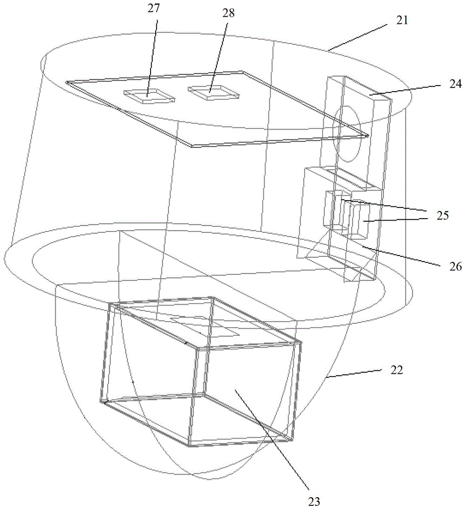
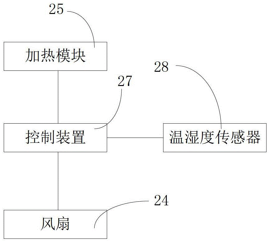
[0014] figure 2 It is a structural schematic diagram of a spherical camera shown in this embodiment. The dome camera includes: a casing 21 , a dome cover 22 , a core 23 , a control device 27 , a temperature and humidity sensor 28 , a heating module 25 and a fan 24 . The dome cover 22 is a transparent cover. When the lens of the movement is shooting an image, if the dome cover is foggy, it will have a great impact on the image clarity. see further image 3 , image 3 It is a control logic diagram of a defogging system. The defogging system includes: a control device 27 , a temperature and humidity sensor 28 , a heating module 25 and a fan 24 . The temperature and humidity sensor senses the temperature and humidity inside the camera. The temperature and humidity sensor here may be an integrated temperature and humidity sensor, or may be a combinat...


PUM


Abstract

The invention discloses a defogging system of a camera. The defogging system is characterized by comprising a control device, a temperature and humidity sensor, a heating module and a fan, wherein the temperature and humidity sensor senses the temperature and humidity in the camera; the control device is used for acquiring temperature T0 and humidity R0 sensed by the temperature and humidity sensor, and calculating dew-point temperature T1 according to the temperature T0 and the humidity R0; the control device is used for calculating surface temperature T2 of window glass according to the temperature T0, T2=T0-delta T, wherein delta T is a constant temperature difference value obtained through heat test; when the T2 is less than T1, the heating module and the fan are controlled to start to work by the control device; and when the T2 is greater than the T1, the heating module and the fan are controlled not to start to work the control device. With the adoption of the defogging system of the camera disclosed by the invention, the camera can be automatically defogged; and the the defogging system of the camera is convenient to control and good in defogging effect.

Description

technical field [0001] The invention relates to cameras in the monitoring field, in particular to a camera defogging system. Background technique [0002] When the ambient temperature of the camera drops rapidly, the surface temperature of the dome cover or window glass used by the camera will also drop. When the hot and humid air inside the camera meets the cold dome cover or window glass, the inner surface will be fogged, which will affect the monitoring and shooting effect. One way to solve the above problems is the vacuum anti-fog method. refer to figure 1 , The camera includes: a housing 1, a right glass 2, a left glass 3, a left pressing plate 4, a right pressing plate 5, and a small vacuum hole 6. Just form a vacuum insulation layer 7 between two layers of glass like this, thereby prevents window from fogging. However, the vacuuming process is relatively complicated, and the airtight performance of the entire device will deteriorate after a long period of use, the...

Claims


Application Information

Patent Timeline
IPC IPC(8): G03B17/55H04N5/232
Inventor 徐燕飞
Owner ZHEJIANG UNIVIEW TECH
Why Eureka
Try Eureka