
Semiconductor chip stacking structure

A chip stacking and semiconductor technology, applied in semiconductor devices, semiconductor/solid-state device components, electric solid-state devices, etc., can solve problems such as reducing package volume and increasing chip stacking density

Active Publication Date: 2012-11-21
ADVANCED SEMICON ENG INC
View PDF3 Cites 20 Cited by
  • Summary
  • Abstract
  • Description
  • Claims
  • Application Information

AI Technical Summary

Problems solved by technology

[0009] In view of this, the present invention provides a semiconductor chip stacking structure to solve the problem that the existing chip stacking technology cannot simultaneously increase the chip stacking density and reduce the packaging volume

Method used


Image

  • Semiconductor chip stacking structure
  • Semiconductor chip stacking structure
  • Semiconductor chip stacking structure

Examples


Embodiment Construction

[0020] The following descriptions of the various embodiments refer to the accompanying drawings to illustrate specific embodiments in which the present invention can be practiced. Furthermore, the directional terms mentioned in the present invention, such as "upper", "lower", "top", "bottom", "front", "back", "left", "right", "inside", " Outer, Side, Surround, Center, Horizontal, Horizontal, Vertical, Longitudinal, Axial, Radial, Topmost, or Bottommost etc. are merely for reference to the directions of the attached drawings. Therefore, the directional terms used are used to illustrate and understand the present invention, but not to limit the present invention.

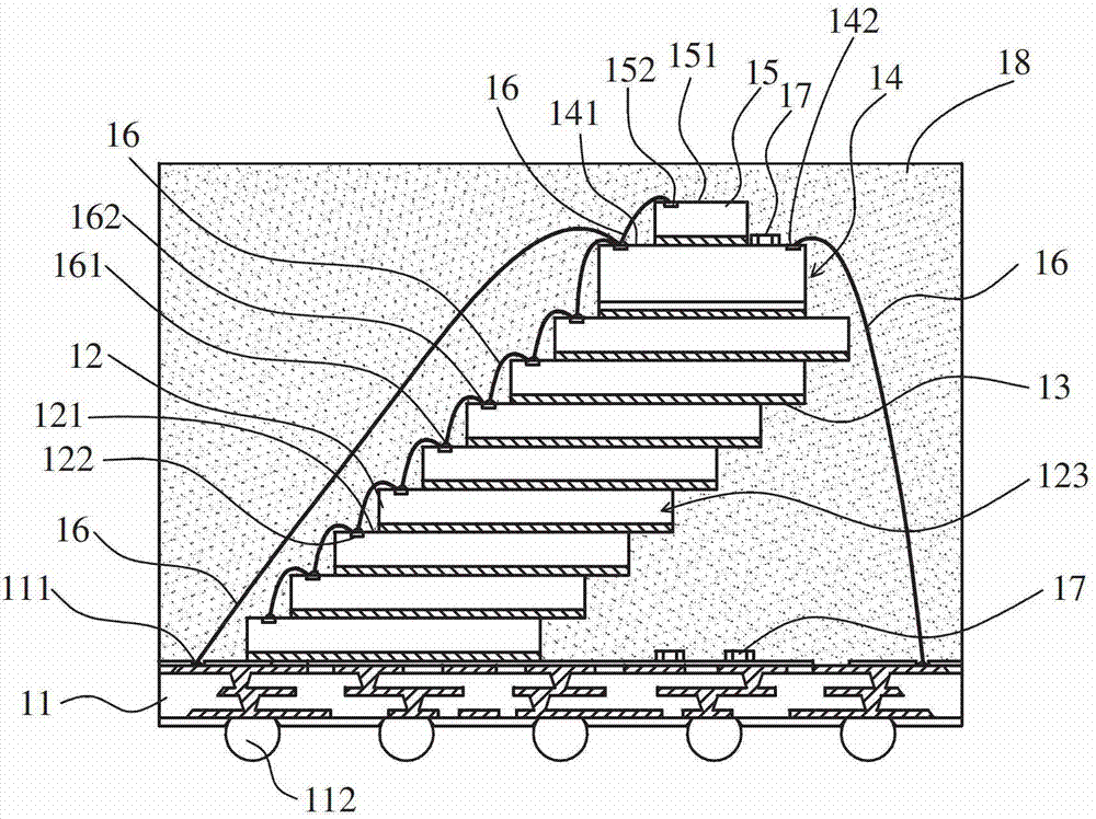
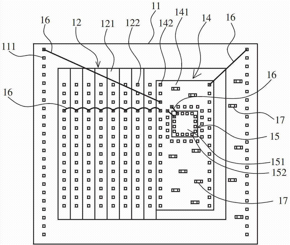
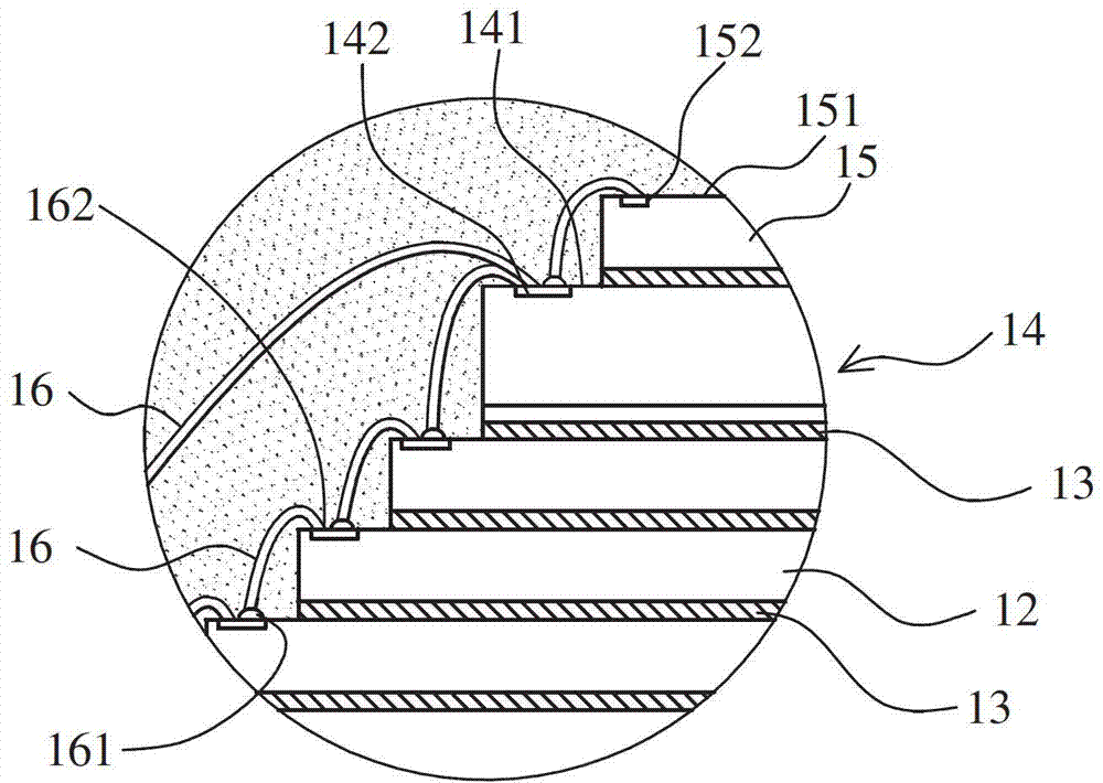
[0021] Please refer to figure 1 As shown, the semiconductor chip stack structure of an embodiment of the present invention is mainly applied to the manufacture of a multi-chip module (MCM), wherein the semiconductor chip stack structure of this embodiment generally includes: a base substrate 11, at least two first c...


PUM

PropertyMeasurementUnit
Widthaaaaaaaaaa

Abstract

The invention discloses a semiconductor chip stacking structure. A plurality of first chips are stacked, the first chips are arrayed in a stepped stacking manner, a dielectric board is arranged on the first chip on the uppermost layer, a second chip is further arranged on the dielectric board, the first chips are upwards and electrically connected with the dielectric board firstly, and then the dielectric board is electrically connected to a bottom substrate. Therefore, the dielectric board can collect the signals of all chips and transmit the signals to the bottom substrate through less electrical connecting components (such as conducting wires), the number of connecting pads needed by the substrate is relatively reduced, so that the length and width of the substrate can be reduced, and further, the stacking density of the chips is increased, and the packaging size is reduced.

Description

technical field [0001] The present invention relates to a semiconductor chip stacking structure, in particular to a semiconductor chip stacking structure with an interposer. Background technique [0002] Nowadays, in order to meet various high-density packaging requirements, the semiconductor packaging industry has gradually developed various types of packaging structures, among which various system in package (SIP) design concepts are often used to build high-density packaging structures. Generally speaking, system packaging can be divided into multi chip module (MCM), package on package (POP) and package in package (PIP). The multi-chip module (MCM) refers to arranging several chips on the same substrate. After setting the chips, the same packaging gel is used to embed all the chips, and according to the arrangement of the chips, it can be subdivided into stacked chips (stacked chips). die) package or parallel chip (side-by-side) package. [0003] Furthermore, in order t...

Claims


Application Information

Patent Timeline
IPC IPC(8): H01L25/065H01L23/538H01L23/31
CPCH01L2924/15311H01L2224/73265H01L2224/32145H01L2225/06562H01L2224/48227H01L2224/32225H01L2224/48145H01L2924/30107H01L24/73
Inventor 林姿君吴汉丁
Owner ADVANCED SEMICON ENG INC
Learn More