Multiple-wave beam antenna

A technology of multi-beam antenna and microstrip antenna, which is applied in the direction of antenna, waveguide opening, electrical components, etc., can solve the problems of complex design and large volume of multi-beam antenna, and achieve the effect of simple design and compact structure

Inactive Publication Date: 2010-05-12
BEIJING JINGWEI HIRAIN TECH CO INC
View PDF0 Cites 19 Cited by
  • Summary
  • Abstract
  • Description
  • Claims
  • Application Information

AI Technical Summary

Problems solved by technology

[0007] The present invention is proposed in view of the problem that the multi-beam antenna has a large volume and a relatively complicated design. Therefore, the main purpose of the present invention is to provide a multi-beam antenna to solve the above problems

Method used


Image

  • Multiple-wave beam antenna
  • Multiple-wave beam antenna

Examples


Embodiment

[0032] According to an embodiment of the present invention, a multi-beam antenna is provided.

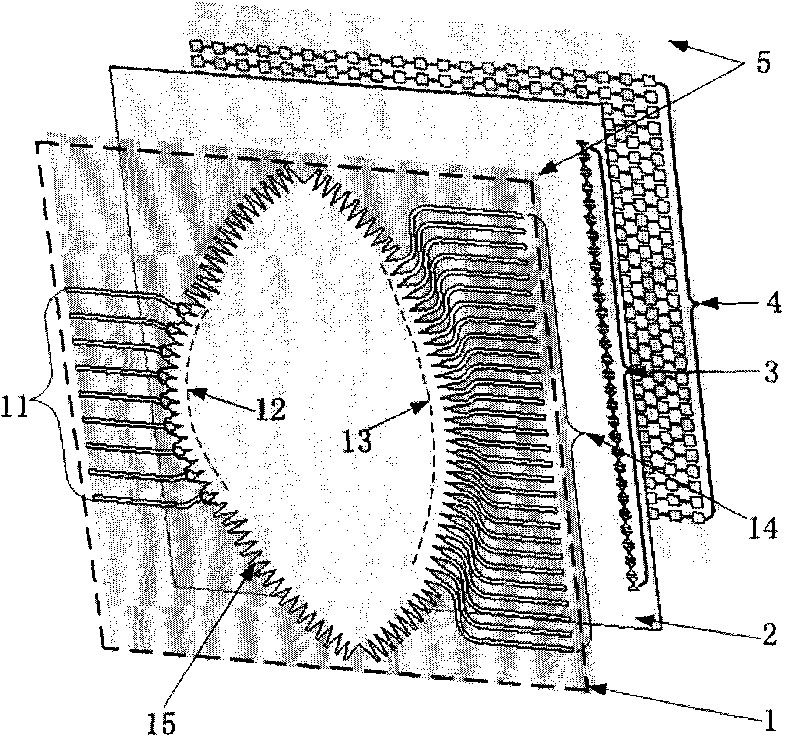
[0033] figure 1 is a schematic diagram of a multi-beam antenna according to an embodiment of the present invention.

[0034] Such as figure 1 As shown, the multi-beam antenna includes: a microstrip Rotman lens 1 , a shielding layer 2 and a microstrip antenna array 4 .

[0035] Wherein, the microstrip Rotman lens 1 includes an input port 11 , an input end arc 12 , an output end arc 13 , an output port 14 , and a matching port 15 . There are multiple openings 3 on the shielding layer 2 . The microstrip antenna array 4 and the microstrip Rotman lens 1 also have a dielectric layer 5 .

[0036] In this embodiment, the microstrip Rotman lens 1 is coupled and connected with the microstrip antenna array 4 to form a multi-beam antenna. The Rotman lens 1 is composed of a dielectric layer 5 and a metal copper-clad surface thereon. From different input ports, different phase difference di...


PUM


Abstract

The invention discloses a multiple-wave beam antenna which comprises a micro-strip Rotman lens, a micro-strip antenna array and a shielding layer, wherein the shielding layer is positioned between the micro-strip Rotman lens and the micro-strip antenna array, provided with a plurality of openings and used for conducting an electromagnetic wave between the micro-strip Rotman lens and the micro-strip antenna array by the shielding layer. The invention solves the problems of larger size and more complicated design of the multiple-wave beam antenna, thereby achieving the effects of compact structure and simple design.

Description

technical field [0001] The present invention relates to the communication field, in particular to a multi-beam antenna. Background technique [0002] Millimeter-wave multi-beam antennas are widely used in communication systems. It can be used in satellite communication systems, various aerospace vehicles, communication systems between mobile transceivers, air or ground traffic control management systems, radar or electronic countermeasure systems, Global Positioning System (Global Position System, referred to as GPS) systems, etc. [0003] There are mainly two ways to implement multi-beam antennas: phased array antennas and multi-beam antennas. Phased array antennas are complex to implement due to the large number of integrated phase shifters, power splitters or directional couplers. The Rotman lens is a multi-beam forming network, and has the advantages of compact structure, easy control of beam pointing, and wide operating bandwidth. However, with the gradual increase i...

Claims


Application Information

Patent Timeline
Patent Type & Authority Applications(China)
IPC IPC(8): H01Q13/08H01Q13/06H01Q19/06H01Q3/46
Inventor 任春张峰会刘敏
Owner BEIJING JINGWEI HIRAIN TECH CO INC
Why Eureka
Try Eureka