Design method for grid electrode with gradually changed width

A technology of electrode design and width gradient, applied in circuits, electrical components, sustainable manufacturing/processing, etc., can solve the problems of complicated calculation process, wrong optimal grid structure criteria, large deviation of mathematical and physical models, etc.

Inactive Publication Date: 2012-11-21
PEKING UNIV
View PDF3 Cites 7 Cited by
  • Summary
  • Abstract
  • Description
  • Claims
  • Application Information

AI Technical Summary

Problems solved by technology

[0014] The purpose of the present invention is to solve the problems in the existing design method of gradually changing grid line electrodes, such as large deviation of mathematical and physical models, wrong optimal grid l

Method used


Image

  • Design method for grid electrode with gradually changed width
  • Design method for grid electrode with gradually changed width
  • Design method for grid electrode with gradually changed width

Examples


Embodiment Construction

[0044] The technical solution of the present invention will be described in further detail below in conjunction with the accompanying drawings and examples, and the following examples do not constitute a limitation to the present invention.

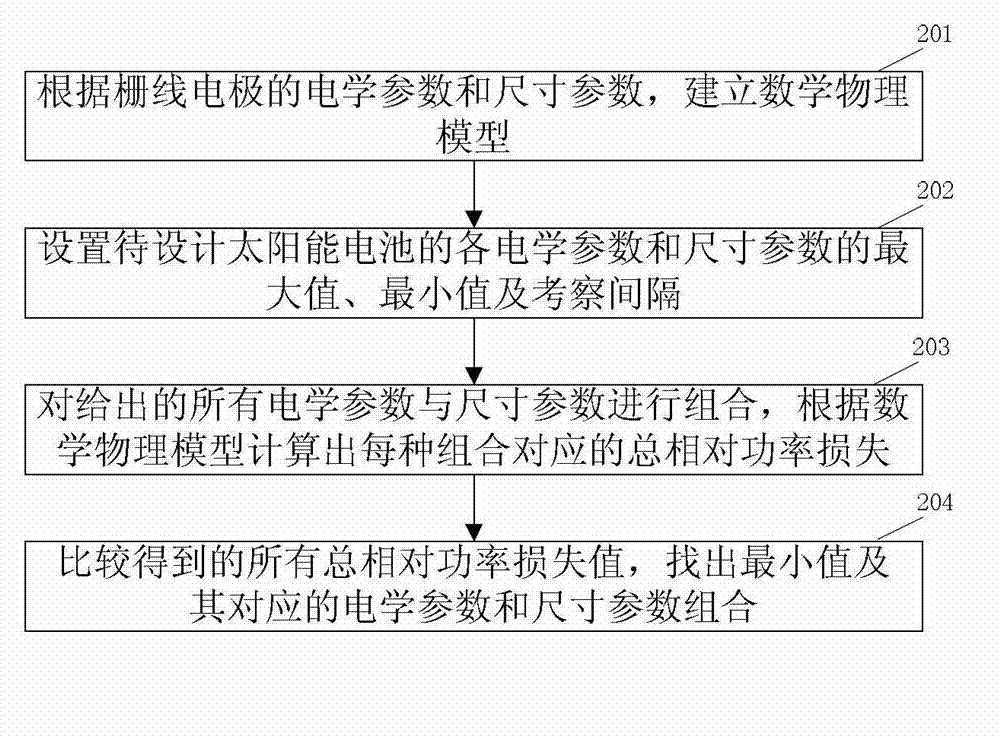
[0045] A method for designing grid line electrodes with gradually changing widths in the present invention, the flow chart of which is as follows figure 2 shown, including the following steps:

[0046] Step 201, establishing a mathematical physical model according to the electrical parameters and size parameters of the grid electrode.

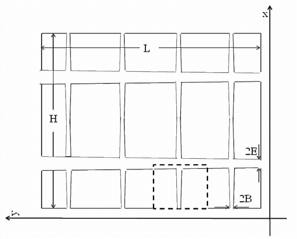
[0047] Specifically, the parameters involved in the grid electrode with gradually changing width include electrical parameters and size parameters. Among them, the electrical parameters include: the output voltage V and current density J at the maximum power point, the square resistance of the film R, the contact resistivity Q between the film and the grid line, and the resistivity G of the grid line; the ...


PUM


Abstract

The invention discloses a design method for a grid electrode with a gradually changed width. The design method comprises the following steps: establishing a mathematical physical model for total relative power loss generated during the process of collecting current carriers of the grid electrode according to parameters of a to-be-designed solar battery; presetting a maximum value, a minimum value and a reference interval of the parameters; combining the given parameters and calculating the total relative power loss corresponding to each combination according to the mathematical physical model; and searching for the minimum value of the total relative power loss and the corresponding parameter combination, wherein the parameter combination corresponding to the minimum value is the optimal grid electrode structure of the solar battery. The design method provided by the invention is less in calculated amount, is simple and practical and is accurate in result.

Description

technical field [0001] The invention belongs to the technical field of solar photovoltaic cells, and in particular relates to a design method for grid line electrodes with gradually changing widths of solar photovoltaic cells. Background technique [0002] As a clean and renewable energy utilization method, solar photovoltaic power generation technology has developed rapidly in recent years. The structure of the grid electrode on the surface of the solar cell has a great influence on the output power of the cell, and is an important link in the design of the solar cell. During the working process of the solar cell, the carriers in the semiconductor thin film are transported to the sub-gate electrode along the direction perpendicular to the sub-gate electrode, then transported to the main gate electrode through the sub-gate electrode, and exported through the main gate electrode. Due to the existence of resistance, the carriers generate a corresponding power loss in the semi...

Claims


Application Information

Patent Timeline
IPC IPC(8): H01L31/18
CPCY02P70/50
Inventor 王东张晓勇赵书力彭海涛于平荣
Owner PEKING UNIV
Why Eureka
Try Eureka