Iron casing structure for liquid crystal module

A liquid crystal module and iron shell technology, applied in the field of liquid crystal display equipment, can solve the problems of difficulty in dismantling iron shells, size differences, waste of iron materials, etc., and achieve the effect of saving raw materials, convenient assembly, and easy disassembly and heavy work

Inactive Publication Date: 2012-11-21
AU OPTRONICS (XIAMEN) CORP +1
View PDF0 Cites 0 Cited by
  • Summary
  • Abstract
  • Description
  • Claims
  • Application Information

AI Technical Summary

Problems solved by technology

[0003] However, due to the large number of hooks in the lower iron shell, it is difficult to control the dimensions to be consistent with each other in the manufacturing process, which will cause the assembly between the hooks and the slots to not always be successfully matched
For example, some hooks can be smoothly slid into the corresponding card slots to achieve mutual locking, while other hooks cannot be smoothly slid into the corresponding card slots due to size differences caused by the manufacturing process
On the other hand, when reassembling, it is not only difficult to disassemble the iron shell, but also the iron filings formed during the disassembly process will affect the quality of the LCD screen
In addition, a large amount of raw materials will be cut off during the production of the upper iron shell and the lower iron shell, resulting in a considerable waste of iron materials

Method used


Image

  • Iron casing structure for liquid crystal module
  • Iron casing structure for liquid crystal module
  • Iron casing structure for liquid crystal module

Examples


Embodiment Construction

[0022] In order to make the technical content disclosed in this application more detailed and complete, reference may be made to the drawings and the following various specific embodiments of the present invention, and the same symbols in the drawings represent the same or similar components. However, those skilled in the art should understand that the examples provided below are not intended to limit the scope of the present invention. In addition, the drawings are only for schematic illustration and are not drawn according to their original scale.

[0023] The specific implementation manners of various aspects of the present invention will be further described in detail below with reference to the accompanying drawings.

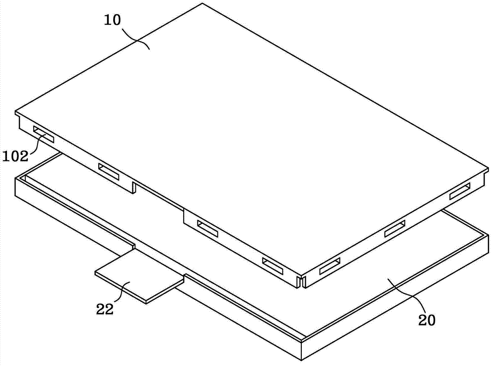
[0024] figure 1 A schematic structural diagram of an iron shell for fixing a liquid crystal module in the prior art is shown. refer to figure 1 , the iron shell structure includes an upper iron shell 10 and a lower iron shell 20 , and the liquid crystal ...


PUM


Abstract

The invention provides an iron casing structure for a liquid crystal module, comprising a first connecting piece and a second connecting piece, wherein the first connecting piece is in an L-shaped structure and is provided with a first horizontal part and a first vertical part; the second connecting piece is in the L-shaped structure and is provided with a second horizontal part and a second vertical part; a rectangular frame is formed by splicing the second connecting piece with the first connecting piece; the area of the rectangular frame is matched with the size of the liquid crystal module; the first horizontal part of the first connecting piece is connected with the second vertical part of the second connecting piece in a screw locking manner; and the first vertical part of the first connecting piece is connected with the second horizontal part of the second connecting piece in a hook buckling manner. With the adoption of the iron casing structure disclosed by the invention, the first connecting piece and the second connecting piece, which are mutually independent in the iron casing structure, are fixedly connected through a mixing manner of screw locking and hook buckling; and therefore, raw materials are saved and the iron casing structure is convenient to assemble, and the problem of the size consistency, caused by overmuch hooks, does not need to be worried.

Description

technical field [0001] The invention relates to a liquid crystal display device, in particular to an iron shell structure used for a liquid crystal module in the liquid crystal display device. Background technique [0002] Currently, in smaller-sized liquid crystal display modules, an assembly method of an upper iron case and a lower iron case is often used to fix the liquid crystal module sandwiched between them. Specifically, a plurality of slots can be provided on the upper iron case, and a plurality of hooks can be provided in positions corresponding to the slots in the lower iron case. When the upper iron case above the liquid crystal module moves downward and approaches the lower iron case At this time, the hooks in the lower iron shell are snapped into the corresponding slots, and then the liquid crystal module is limited in the vertical direction. [0003] However, due to the large number of hooks in the lower iron shell, it is difficult to control the dimensions to...

Claims


Application Information

Patent Timeline
Patent Type & Authority Applications(China)
IPC IPC(8): H05K5/04G02F1/13
Inventor 郑忠明
Owner AU OPTRONICS (XIAMEN) CORP
Why Eureka
Try Eureka