Device for rotational coupling of a crown gear to a wheel and aircraft landing gear provided with such a device

A wheel and axis of rotation technology, applied in the field of aircraft landing gear, can solve problems such as heavy joints and unsuitable for aircraft

Active Publication Date: 2012-11-28
SAFRAN LANDING SYSTEMS
View PDF6 Cites 18 Cited by
  • Summary
  • Abstract
  • Description
  • Claims
  • Application Information

AI Technical Summary

Problems solved by technology

However, these joints are bulky and unsuitable for aircraft

Method used


Image

  • Device for rotational coupling of a crown gear to a wheel and aircraft landing gear provided with such a device
  • Device for rotational coupling of a crown gear to a wheel and aircraft landing gear provided with such a device
  • Device for rotational coupling of a crown gear to a wheel and aircraft landing gear provided with such a device

Examples


Embodiment Construction

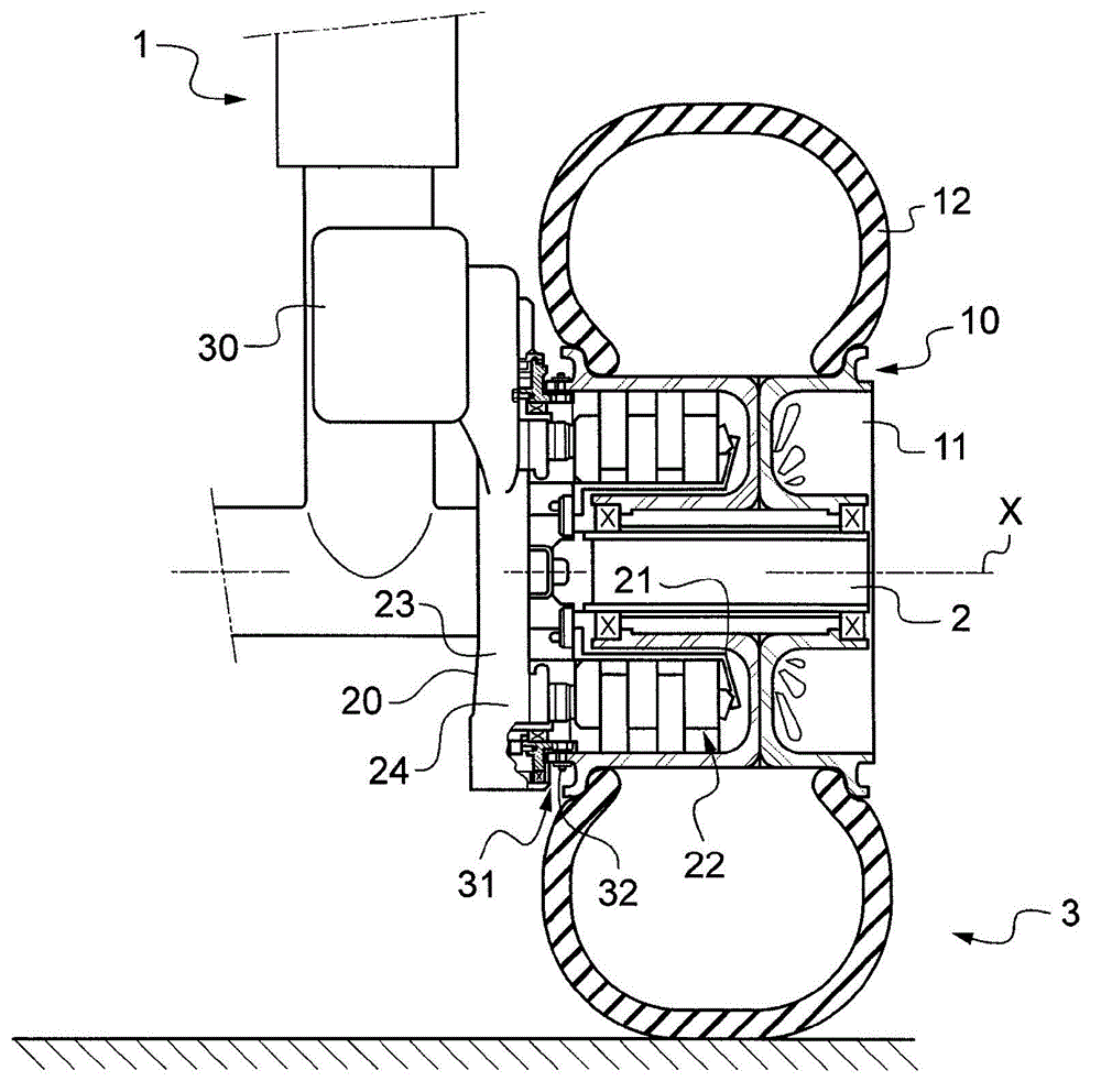
[0018] figure 1 A landing gear 1 of a known type is shown by way of example in order to illustrate the context of the invention. The undercarriage comprises a base with axles 2 for receiving two wheels and brake assemblies 3 on either side of the undercarriage. Only one of these components is shown here.

[0019] Each component includes:

[0020] - a wheel 10 with a rim 11 (here, consisting of two half-rims) receiving a tire 12, the wheel 10 mounted to rotate on the axis 2 about the axis of rotation X by means of rolling bearings;

[0021] - a brake 20 comprising a torsion tube 21, a disc 22 and an actuator mount 23, the torsion tube 21 being bolted to the landing gear so as to be rotatably fixed, the disc 22 between the torsion tube 21 and the rim 11 extending between them so as to be rotatably locked alternately with the rim 11 and the torsion tube 21, the actuator mount 23 is integral with the torsion tube 21 and houses a brake actuator 24, in this case a hydraulic actua...


PUM


Abstract

The invention relates to a device (32) for rotationally coupling a wheel (10) with a ring (31) for driving the wheel (10) mounted so as to rotate coaxially with the wheel (10). According to the invention, the device (32) comprises a plurality of connecting members (60) each extending in a direction contained in a plane perpendicular to the axis of rotation and forming an angle with a radial direction, the connecting members (60) being pivotably mounted on the one hand on the wheel (10) and on the other hand on the ring (31).

Description

technical field [0001] The present invention relates to a device for rotationally engaging a ring with a wheel, and to an aircraft landing gear equipped with such a device. Background technique [0002] In order to reduce the fuel consumption as well as the noise level and pollution produced by jet engines running on the ground, it has been proposed to add power to the wheels of an aircraft so that the aircraft can move within the airport area without the aid of its jet engines. [0003] Thus, the landing gear of an aircraft comprises legs articulated to the aircraft at a first end and mounted at a second end with wheels or trains resting on the ground and equipped with means or means for driving the wheels Taxi motors to move the aircraft, for example, between its parking position and the take-off runway when the aircraft is on the ground. [0004] During landing and take-off, the landing gear is subjected to severe stresses that deform the rims and displace the axes of ro...

Claims


Application Information

Patent Timeline
Patent Type & Authority Applications(China)
IPC IPC(8): B64C25/36
CPCF16D3/62B64C25/405Y02T50/80
Inventor D·布切顿S·瑞蒙德G·艾卢亚德
Owner SAFRAN LANDING SYSTEMS
Why Eureka
Try Eureka