Crankshaft type high-pressure cleaning pump

A technology for high-pressure cleaning of pumps and crankshafts, applied in pumps, multi-cylinder pumps, liquid variable capacity machinery, etc., can solve problems such as damage to related components, short service life, and no product launch.

Inactive Publication Date: 2012-11-28
浙江驰江工贸有限公司
View PDF8 Cites 8 Cited by
  • Summary
  • Abstract
  • Description
  • Claims
  • Application Information

AI Technical Summary

Problems solved by technology

[0003] The current crankshaft-type high-pressure cleaning pump has the following disadvantages during use: First, the structure is complex, the volume is large, the production and processing are difficult, the working pressure stability is poor, and the related parts are easily damaged, and the service life is short
Second, the pressure adjustment accuracy of the pressure regulating and unloading valve is low, the pressure adjustment is not smooth, the unloading sensitivity is poor, and the assembly, maintenance and disassembly are difficult. Due to the unstable unloading pressure, it is easy to cause high pressure between the back end of the valve and the spray gun or nozzle. , resulting in damage to the seal and the nozzle of the spray gun
For this reason, many manufacturers and people of insight have all carried out development and research, but do not have ideal product to come out so far

Method used


Image

  • Crankshaft type high-pressure cleaning pump
  • Crankshaft type high-pressure cleaning pump
  • Crankshaft type high-pressure cleaning pump

Examples


Embodiment Construction

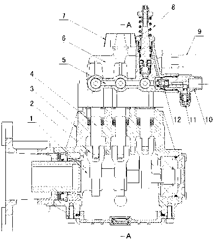
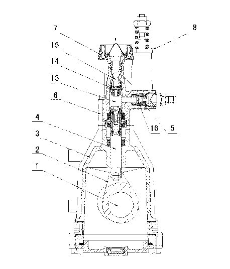
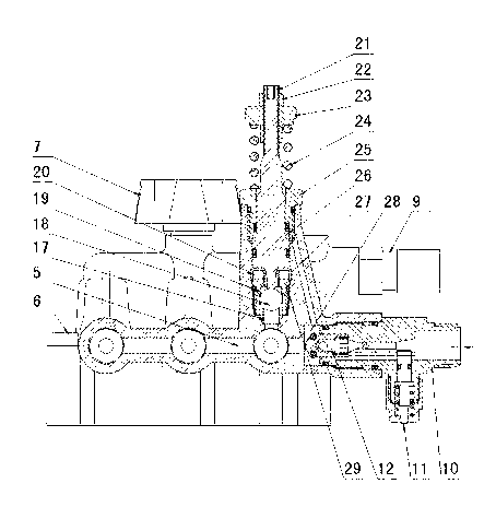
[0014] figure 1 , figure 2 and image 3 As shown, the specific embodiment of the crankshaft type high-pressure cleaning pump created for the present invention includes a box body 3, a crankshaft 1 connected with power, a connecting rod 2, a plunger 4, a pump body 6, a water inlet joint 7, a pressure regulating discharge Load valve 8, high-pressure water outlet joint 10, the pump body 6 is provided with a low-pressure chamber 15, an exchange chamber 13 and a high-pressure chamber 5, the plunger 4 is connected to the exchange chamber 13, and the water inlet joint 7 is connected to the low-pressure chamber 15 A water inlet check valve 14 is installed between the low pressure chamber 15 and the exchange chamber 13, a water outlet check valve 16 is installed between the exchange chamber 13 and the high pressure chamber 6, and the high pressure outlet joint 10 is connected to the water outlet of the high pressure chamber 5 Above, a check valve 12 corresponding to the water outlet...


PUM


Abstract

The invention discloses a crankshaft type high-pressure cleaning pump. The crankshaft type high-pressure cleaning pump comprises a box body (3), a crankshaft (1) connected with a power, a connecting rod (2), a plunger piston (4), a pump body (6), a water supply connector (7), a pressure regulating unloading valve (8) and a high-pressure water discharging connector (10), wherein a low-pressure cavity (15), an exchange cavity (13) and a high-pressure cavity (5) are arranged in the pump body (6), the plunger piston (4) is connected on an exchange cavity (13), the water supply connector (7) is connected on the low-pressure cavity (15), a water supply check valve (14) is installed between the low-pressure cavity (15) and the exchange cavity (13), a water discharging check valve (16) is installed between the exchange cavity (13) and the high-pressure cavity (6), the high-pressure water discharging connector (10) is connected on a water outlet of the high-pressure cavity (5), a check valve (12) corresponding to a water outlet of the high-pressure cavity (5) is arranged on the high-pressure water discharging connector (10), and the pressure regulating unloading valve (8) is arranged on the high-pressure cavity (5) of the pump body (6). Due to the adoption of the structure, the crankshaft type high-pressure cleaning pump has the advantages that the structure is simple and reasonable, the operation and the use are convenient, the pressure regulation is stable, the pressure is stable, the unloading is flexible, the cleaning pump is used by limiting the pressure, and the service life is long, and the like.

Description

technical field [0001] The invention relates to a high-pressure pump, in particular to a crankshaft-type high-pressure cleaning pump capable of pressure regulation and unloading. Background technique [0002] Crankshaft type high-pressure cleaning pump is a high-efficiency, high-pressure, energy-saving cleaning equipment, widely used in chemical plants, thermal power plants, sugar factories, paper mills and other industries to clean heat exchangers, reactors and various pipelines, and can also be used in various Cleaning of various vehicles, aircraft, ships, slaughterhouses, etc. When working, the power drives the crankshaft to rotate, and the crankshaft drives the plunger to reciprocate through the eccentric rotation of the connecting rod. When the plunger is pulled out, the pressure in the exchange chamber decreases, and the water outlet check valve closes. When the pressure in the exchange chamber is lower than the inlet pressure, the water enters The one-way valve opens...

Claims


Application Information

Patent Timeline
Patent Type & Authority Applications(China)
IPC IPC(8): F04B1/00F04B1/34
Inventor 颜志江
Owner 浙江驰江工贸有限公司
Why Eureka
Try Eureka