Backlight module

A technology of backlight module and LED backlight, which is applied in the field of backlight module, can solve the problems of light leakage, limited adhesive area, and easy floating of LED light strips, so as to enhance the positioning function and avoid uneven light projection Effect

Inactive Publication Date: 2012-11-28
AU OPTRONICS (SUZHOU) CORP LTD +1
View PDF0 Cites 7 Cited by
  • Summary
  • Abstract
  • Description
  • Claims
  • Application Information

AI Technical Summary

Problems solved by technology

[0004] The above two methods can realize the vertical displacement of the LED light bar. However, the positioning of the LED light bar is basically guaranteed by the viscosity and area of ​​the glue. When the FPC (Flexible Printed Circuit, flexible printed circuit) rebounds or When it is not flat, the LED strip is easy to float
In addition, the current product design is to adapt to the trend of thinner and narrower bezels. The adhesive area is limited and the adhesion reliability is not high, which will also cause the LED light bar to float, resulting in light leakage.

Method used


Image

  • Backlight module
  • Backlight module
  • Backlight module

Examples


Embodiment Construction

[0028] In order to make the technical content disclosed in this application more detailed and complete, reference may be made to the drawings and the following various specific embodiments of the present invention, and the same symbols in the drawings represent the same or similar components. However, those skilled in the art should understand that the examples provided below are not intended to limit the scope of the present invention. In addition, the drawings are only for schematic illustration and are not drawn according to their original scale.

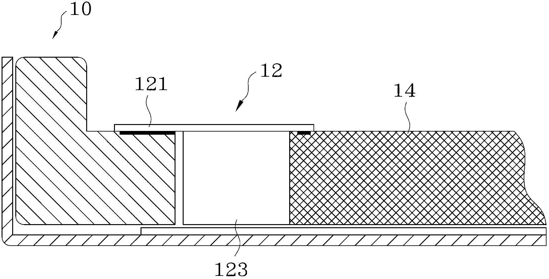
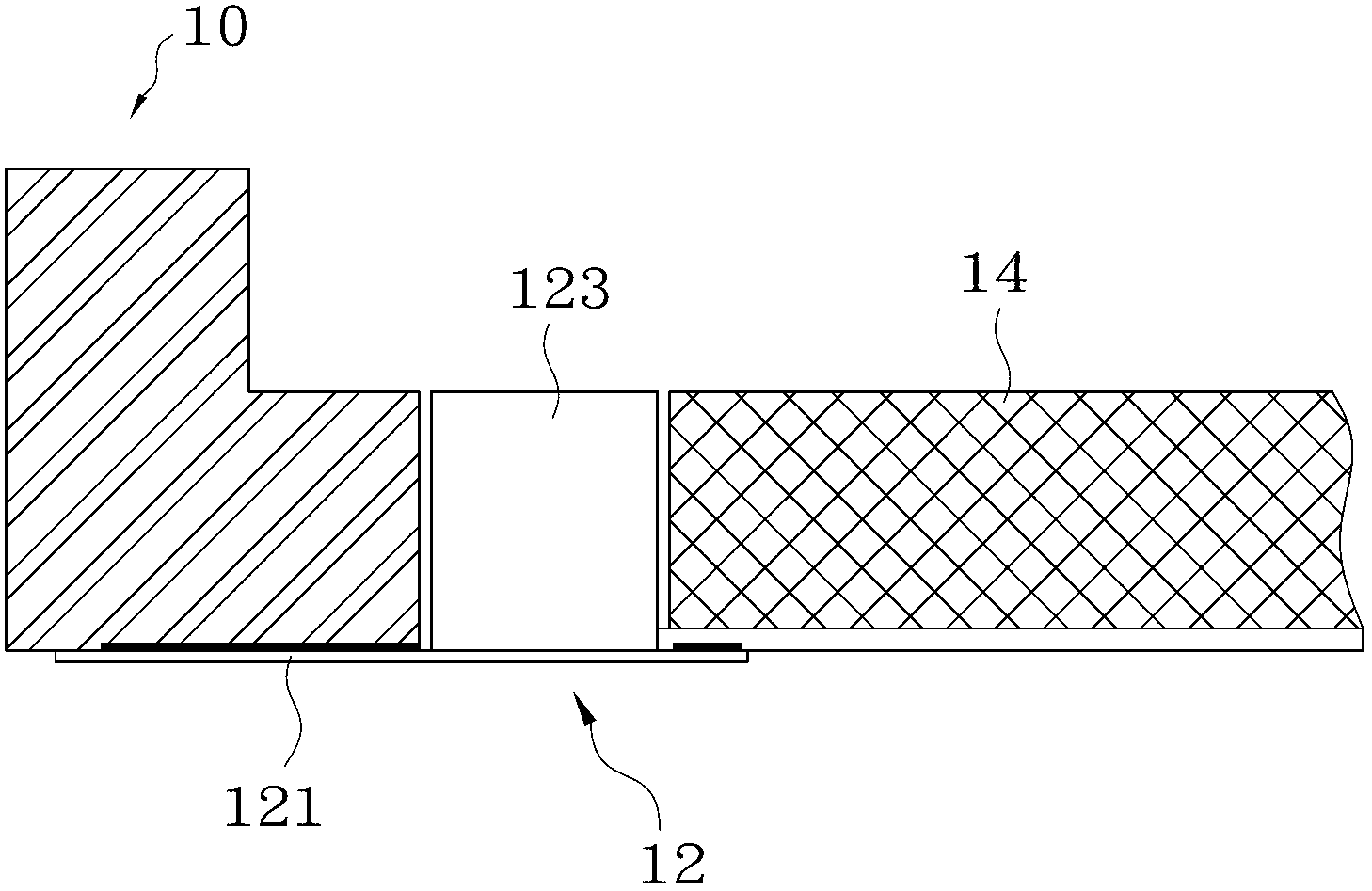
[0029] Figure 1A It is a schematic diagram showing the status of the LED in the traditional backlight module being limited by the way of snapping in from the front. refer to Figure 1A , the backlight module mainly includes a plastic frame 10 , an LED light bar 12 and a light guide plate 14 . Wherein, the LED light bar 12 includes a base plate 121 and an LED light 123 , the base plate 121 extends in the horizontal direction, an...


PUM


Abstract

The invention provides a backlight module which is applicable to positioning of an LED (light-emitting diode) backlight source. The backlight module comprises a rubber frame, a light guiding plate and an LED lamp strip, wherein the rubber frame comprises a bottom and a side wall vertical to the bottom; the side surface of the light guiding plate and the bottom of the rubber frame confine an accommodating space; the LED lamp strip comprises a substrate and at least one LED lamp; the LED lamp is positioned on the bottom surface of the substrate and is arranged inside the accommodating space; and the LED lamp and the bottom of the rubber frame are limited in a concave-convex matching way so as to prevent the LED lamp strip from moving in the vertical direction. By adopting the structure that the LED lamp is arranged inside the accommodating space confined by the bottom of the rubber frame and the side surface of the light guiding plate and the LED lamp and the bottom of the rubber frame are limited in a concave-convex matching way, the LED lamp strip can be prevented from moving in the vertical direction and nonuniform projection of light rays emitted by the LED can be avoided.

Description

technical field [0001] The invention relates to a liquid crystal display device, in particular to a backlight module of the liquid crystal display device. Background technique [0002] At present, the backlight module (Backlight Module) is one of the key components of the liquid crystal display panel. Since the liquid crystal itself does not emit light, the function of the backlight module is to provide sufficient brightness and uniformly distributed light source so that it can display images normally. LCD (Liquid Crystal Display, liquid crystal display) panels have been widely used in monitors, notebook computers, digital cameras and projectors and other electronic products with growth potential. [0003] Specifically, the backlight module mainly consists of a light source (such as cold cathode fluorescent tube CCFL, hot cathode fluorescent tube, light emitting diode, etc.), lampshade, reflector (Reflector), light guide plate (Light Guide Plate, LGP), diffusion sheet (Diffu...

Claims


Application Information

Patent Timeline
Patent Type & Authority Applications(China)
IPC IPC(8): F21S8/00F21V17/10G02F1/13357F21Y101/02
Inventor 肖兵
Owner AU OPTRONICS (SUZHOU) CORP LTD
Why Eureka
Try Eureka