Internal cooling device of oxidized pellet shaft furnace

A cooling device and a technology for oxidizing pellets, which is applied in the field of oxidizing pellet shaft furnaces, and can solve problems such as inability to recover heat, inability to use pellets, and hazards

Active Publication Date: 2012-11-28
JIGANG INT ENG & TECH CO LTD
View PDF5 Cites 0 Cited by
  • Summary
  • Abstract
  • Description
  • Claims
  • Application Information

AI Technical Summary

Problems solved by technology

[0002] In the production process of the oxidizing pellet shaft furnace, the cooling air blown in the cooling zone of the shaft furnace exchanges heat with the roasted pellets and heats up, then mixes with the gas combustion products of the shaft furnace combustion chamber, and realizes the cooling on the shaft furnace drying bed. In the drying and preheating process of the green pellets with a water content of about 8.5%, in order to ensure the integrity of the green pellets, there are strict requirements on the flow rate and temperature of the high-temperature gas passing through the drying bed, so the oxidation balls are blown in The cooling air volume of the pellet shaft furnace needs to be strictly controlled, so that the roasted pellets cannot fully exchange heat with the cooling air, and eventually the discharge temperature of the pellet shaft furnace is as high as ~600°C, and the hot pellets affect the oxidation of the pellet shaft furnace. The toothed rollers, unloaders and subsequent transportation equipment all pose a greater hazard. At the same time, the sensible heat of the pellets is naturally consumed, and its heat cannot be recycled.

Method used


Image

  • Internal cooling device of oxidized pellet shaft furnace
  • Internal cooling device of oxidized pellet shaft furnace

Examples


Embodiment Construction

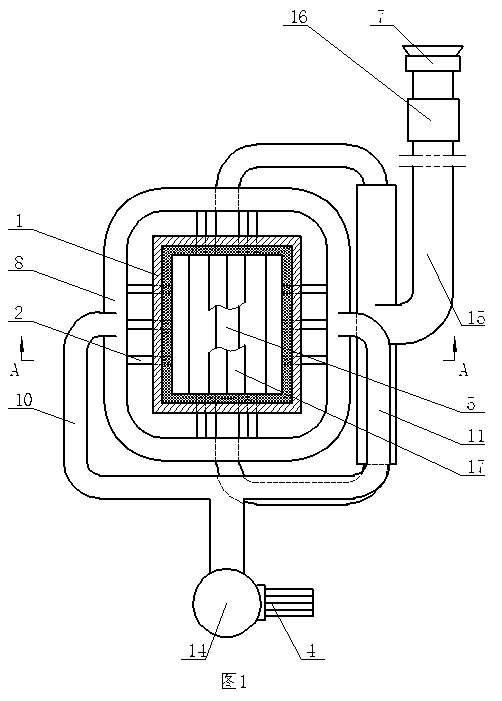
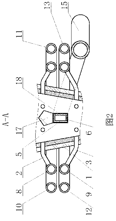
[0007] A built-in cooling device for an oxidation pellet shaft furnace according to the present invention includes a pellet shaft furnace cooling belt shell 1, a plurality of primary cooling air supply branch pipes 2 are evenly arranged on the upper circumference of the side wall of the cooling belt shell 1, and the cooling belt A plurality of secondary cooling air supply branch pipes 3 are evenly arranged around the lower part of the side wall of the housing 1, each of the primary cooling air supply branch pipe 2 and the secondary cooling air supply branch pipe 3 are connected to the blower 4 through pipelines, and the primary cooling air supply branch pipe 2 Cooling wind collecting beams 5 are installed in the cooling belt housing 1 between the secondary cooling air supply branch pipe 3, and a plurality of air collecting holes 6 are arranged on the bottom surface of the cooling wind collecting beams 5, and the two ends of the cooling wind collecting beams 5 are connected with ...


PUM


Abstract

The invention provides an internal cooling device of an oxidized pellet shaft furnace, comprising a cooling zone shell of the pellet shaft furnace, wherein a plurality of primary cooling air supply branch tubes are uniformly arranged on the circumferential ring of the upper part of the sidewall of the cooling zone shell; a plurality of secondary cooling air supply branch tubes are uniformly arranged on the circumferential ring of the lower part of the sidewall of the cooling zone shell; each of the primary cooling air supply branch tubes and each of the secondary cooling air supply branch tubes are connected with an air blower via pipelines; a cooling air collection beam is installed in the cooling zone shell between the primary cooling air supply branch tubes and the secondary cooling air supply branch tubes; a plurality of air collection holes are formed in the bottom surface of the cooling air collection beam; both ends of the cooling air collection beam are connected with an air collection main tube via pipelines; and the air collection main tube is connected with a negative-pressure fan. According to the invention, the ore discharge temperature of the pellet shaft furnace can be effectively reduced, the service life of equipment can be prolonged, and the heat carried by pellet ores can be recycled simultaneously.

Description

technical field [0001] The invention relates to an oxidation pellet shaft furnace, in particular to a built-in cooling device for an oxidation pellet shaft furnace. Background technique [0002] In the production process of the oxidizing pellet shaft furnace, the cooling air blown in the cooling zone of the shaft furnace exchanges heat with the roasted pellets and heats up, then mixes with the gas combustion products of the shaft furnace combustion chamber, and realizes the cooling on the shaft furnace drying bed. In the drying and preheating process of the green pellets with a water content of about 8.5%, in order to ensure the integrity of the green pellets, there are strict requirements on the flow rate and temperature of the high-temperature gas passing through the drying bed, so the oxidation balls are blown in The cooling air volume of the pellet shaft furnace needs to be strictly controlled, so that the roasted pellets cannot fully exchange heat with the cooling air,...

Claims


Application Information

Patent Timeline
Patent Type & Authority Applications(China)
IPC IPC(8): F27B1/24
Inventor 赵忠文戚云峰李兵
Owner JIGANG INT ENG & TECH CO LTD
Why Eureka
Try Eureka