

Flow distribution structure of reactor of nuclear power station
A nuclear power plant reactor and flow distribution technology, which is applied in the field of nuclear power, can solve the problems of complex structure, large number of connecting bolts, and high cost, and achieve the effects of avoiding vortex shedding, good flow distribution uniformity, and improving flow field characteristics
- Summary
- Abstract
- Description
- Claims
- Application Information
AI Technical Summary
Problems solved by technology
Method used
Image

Examples
Embodiment Construction
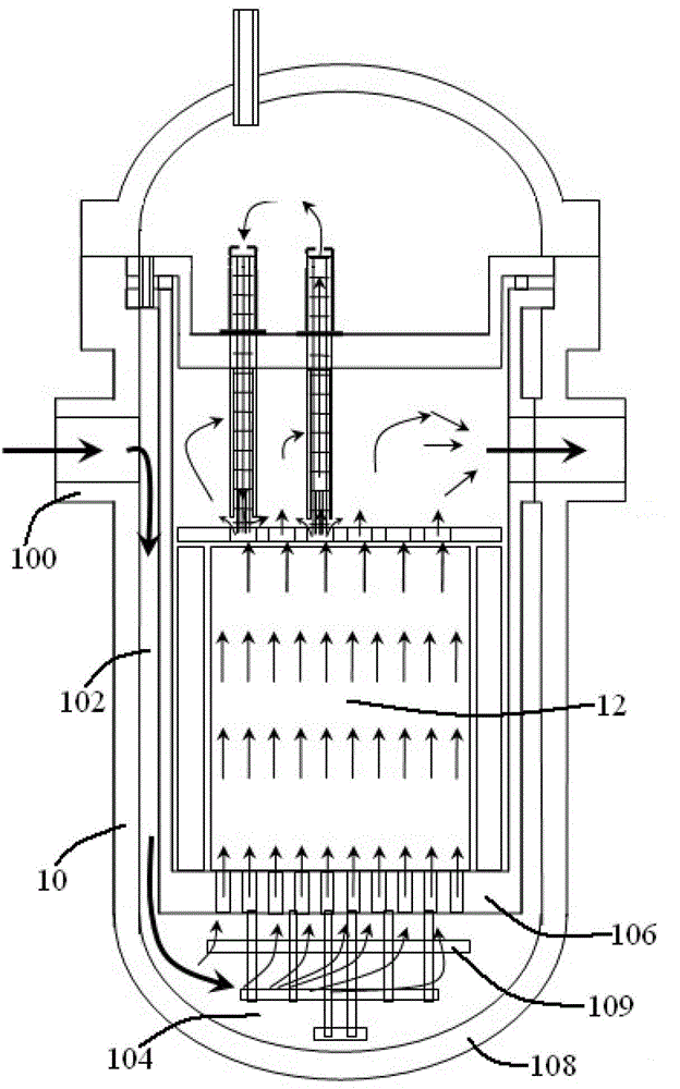
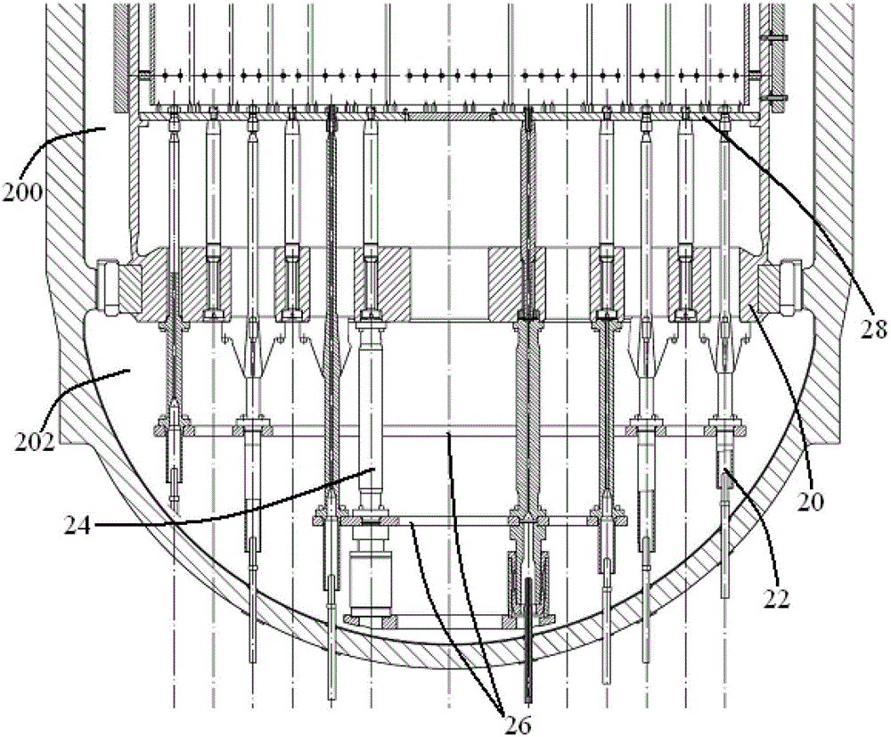
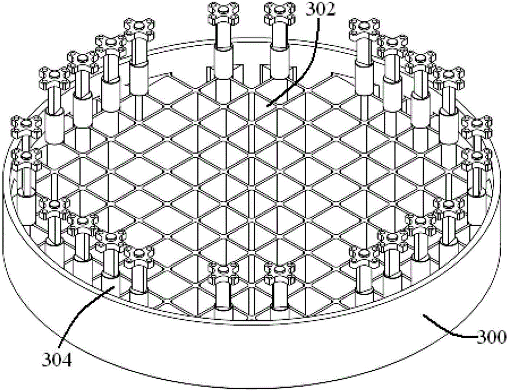
[0025] see Figure 5 and Figure 6 , The flow distribution structure of the nuclear power plant reactor of the present invention includes a support plate 50 under the core and a head-shaped structure.
[0026] The lower support plate 50 of the core is welded to the lower end of the hanging basket 80, and has a perforation 52 corresponding to the position of each fuel assembly.
[0027] The head-shaped structure includes a head 60 and a flange 62 . Among them, the head 60 is hemispherical, with a thickness of 20-150 mm, and a large number of flow holes 600 with a diameter of 20-200 mm are evenly opened on it. These flow holes 600 include vertical flow holes 602, horizontal flow holes 604 and oblique flow holes. Hole 606. The flange 62 is arranged on the edge of the head 60, and several screw holes 620 are opened on it, and the bolts 64 pass through the screw holes 620 on the flange 62 to fix the head-shaped structure on the edge of the lower surface of the core lower support...
PUM
| Property | Measurement | Unit |
|---|---|---|
| Thickness | aaaaa | aaaaa |
Abstract
Description
Claims
Application Information