Shell and tube heat exchanger

A technology of shell-and-tube heat exchangers and heat exchange tubes, which is applied in the direction of heat exchanger types, indirect heat exchangers, lighting and heating equipment, etc., and can solve the problem of reducing heat exchange tube cutting, flat tube work, and U-shaped tubes Difficult assembly, scratches on heat exchange tubes, etc., to achieve good flow field characteristics, high cost performance, and improved efficiency

Active Publication Date: 2015-03-11
DONGFANG TURBINE CO LTD
View PDF4 Cites 0 Cited by
  • Summary
  • Abstract
  • Description
  • Claims
  • Application Information

AI Technical Summary

Problems solved by technology

[0005] The purpose of the present invention is to: provide a shell-and-tube heat exchanger, update its internal structure, solve the problem of scratching the heat exchange tubes in the existing fixed position-limiting structure, and difficult assembly of U-shaped piping systems, and reduce (or Avoid) cutting and flattening the limited heat exchange tubes

Method used


Image

  • Shell and tube heat exchanger
  • Shell and tube heat exchanger

Examples


Embodiment Construction

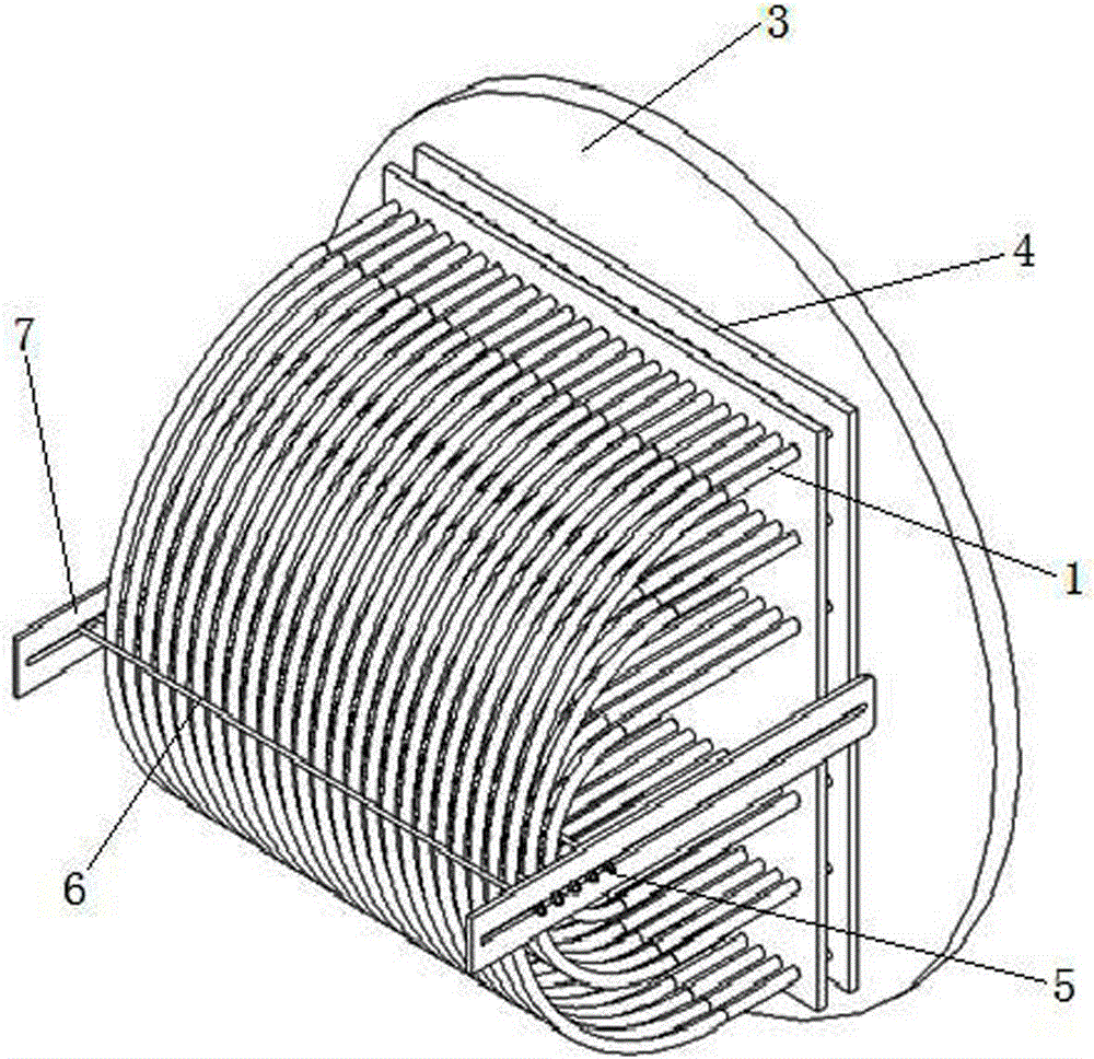
[0016] The invention is a shell-and-tube heat exchanger, which is provided with a U-shaped heat exchange tube system arranged in n layers from the inside to the outside. On the end tube plate 3. In this specific embodiment, the U-shaped heat exchange tube system has 3 layers, and the U-shaped heat exchange tube 1 of each layer increases in length and outline from the inside to the outside, and its number and shape can be designed and changed according to heat exchange needs.

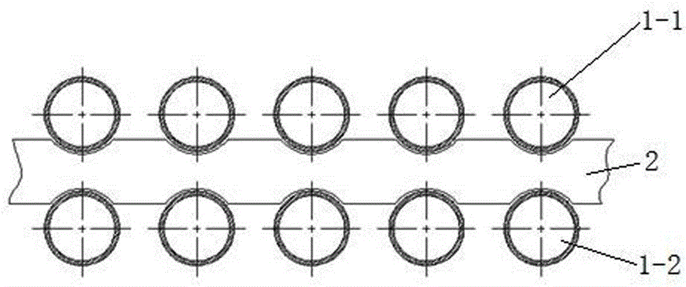
[0017] figure 2 The structural form of the sliding anti-collision limiting device of the U-shaped heat exchange tube system in the shell-and-tube heat exchanger of the present invention is described in detail in , and its use and assembly structure with the U-shaped heat exchange tube 1 is described in detail. Such as figure 2 As shown, an anti-collision limiting device is provided between each layer of U-shaped heat exchange tubes 1 , and the anti-collision limiting device includes a positioning pla...


PUM


Abstract

The invention provides a shell and tube heat exchanger. A U-shaped heat exchange tube system arranged in n layers from the inside to the outside is arranged in the heat exchanger, the layers of the U-shaped heat exchange tubes are arranged in parallel, and two ends are fixedly connected with a tube system end tube plate. An anti-collision limit unit is arranged between the layers of the U-shaped heat exchange tubes respectively and comprises two location plates and n+1 separation rods. The two location plates are arranged on the two sides of the U-shaped heat exchange tube system, and the ends are fixedly connected with the tube system end tube plate. Installation grooves of the separation rods are formed in the corresponding positions in the two location plates which are detachably connected with the separation rods, and the separation rods are arranged before and after each layer of the U-shaped heat exchange tubes to separate the adjacent U-shaped heat exchange tubes. The shell and tube heat exchanger has the advantages that good flow field characteristics are provided, and vortexes are reduced; limit is performed effectively, and scratching of the tube walls is prevented; the requirement for assembly size is not high, and the practicality is high; the limit is flexible, cutting and tube flattening processes of tube sections are reduced, the efficiency is improved, the cost is reduced, and the cost performance is high.

Description

technical field [0001] The invention relates to a shell-and-tube heat exchanger, in particular to an improvement to the internal structure of the shell-and-tube heat exchanger of a large-scale low-pressure heater in a power station using a U-shaped heat exchange piping system. Background technique [0002] At present, the anti-collision limiting device of the U-shaped heat exchange tube of the low-pressure heater tube system designed and manufactured by domestic low-pressure heater manufacturers generally adopts a half-hole sheet lap joint fixed structure. Such as figure 1 As shown, that is, the half-hole sheet 2 made of thin steel strips is overlapped between each layer of U-shaped heat exchange tubes 1, that is, there are several half-hole grooves on both sides of the half-hole sheet 2 for the first The first layer of U-shaped heat exchange tubes 1-1 and the second layer of U-shaped heat exchange tubes 1-2 are installed, and both ends are fixedly installed in the shell-an...

Claims


Application Information

Patent Timeline
Patent Type & Authority Applications(China)
IPC IPC(8): F28D7/06
Inventor 邓富军季丹周刚刘维信杜立刚汤精忠巩昌强
Owner DONGFANG TURBINE CO LTD
Why Eureka
Try Eureka