
Electric operation mechanism of switch

A technology of electric operating mechanism and manual operation, applied to the power device inside the switch, etc., can solve the problems of low product safety and reliability, many parts, complicated mechanism, etc., and achieve the effect of safe and reliable product performance

Active Publication Date: 2012-11-28
SHANGHAI GOOD FAITH ICEST
View PDF6 Cites 13 Cited by
  • Summary
  • Abstract
  • Description
  • Claims
  • Application Information

AI Technical Summary

Problems solved by technology

At present, there are existing products similar to electric operating mechanisms at home and abroad, such as international companies such as Schneider and ABB, domestic companies such as Suzhou Future Electric Co., Ltd., and Wuxi Kaixuan Motor Co., Ltd., all produce products of electric operating mechanisms, but these existing Technology products have the following common defects: complex mechanism, many parts, cumbersome assembly process, and low production efficiency; due to complex mechanism and many parts, product failure rate is high, quality stability is poor, and life is short; Unreasonable layout of components leads to problems such as large product size, low space utilization, low product safety and reliability, high noise, and large vibration
In the electric operating mechanisms of the prior art, some need to use servo motors or stepping motors as control actuators. The disadvantages are: the cost of servo motors or stepping motors is high, and complex control circuits need to be configured; the control circuits are unidirectional To control the action of the servo motor or stepping motor, and to monitor the closing / breaking state of the circuit breaker in real time, it is necessary to add sensors and monitoring circuits, so the mechanical and electrical structures are very complicated.

Method used


Image

  • Electric operation mechanism of switch
  • Electric operation mechanism of switch
  • Electric operation mechanism of switch

Examples


Embodiment Construction

[0031] The implementation of the present invention will be described in detail below with reference to the accompanying drawings, and the electric operating mechanism of the switch of the present invention is not limited to the description of the following embodiments.

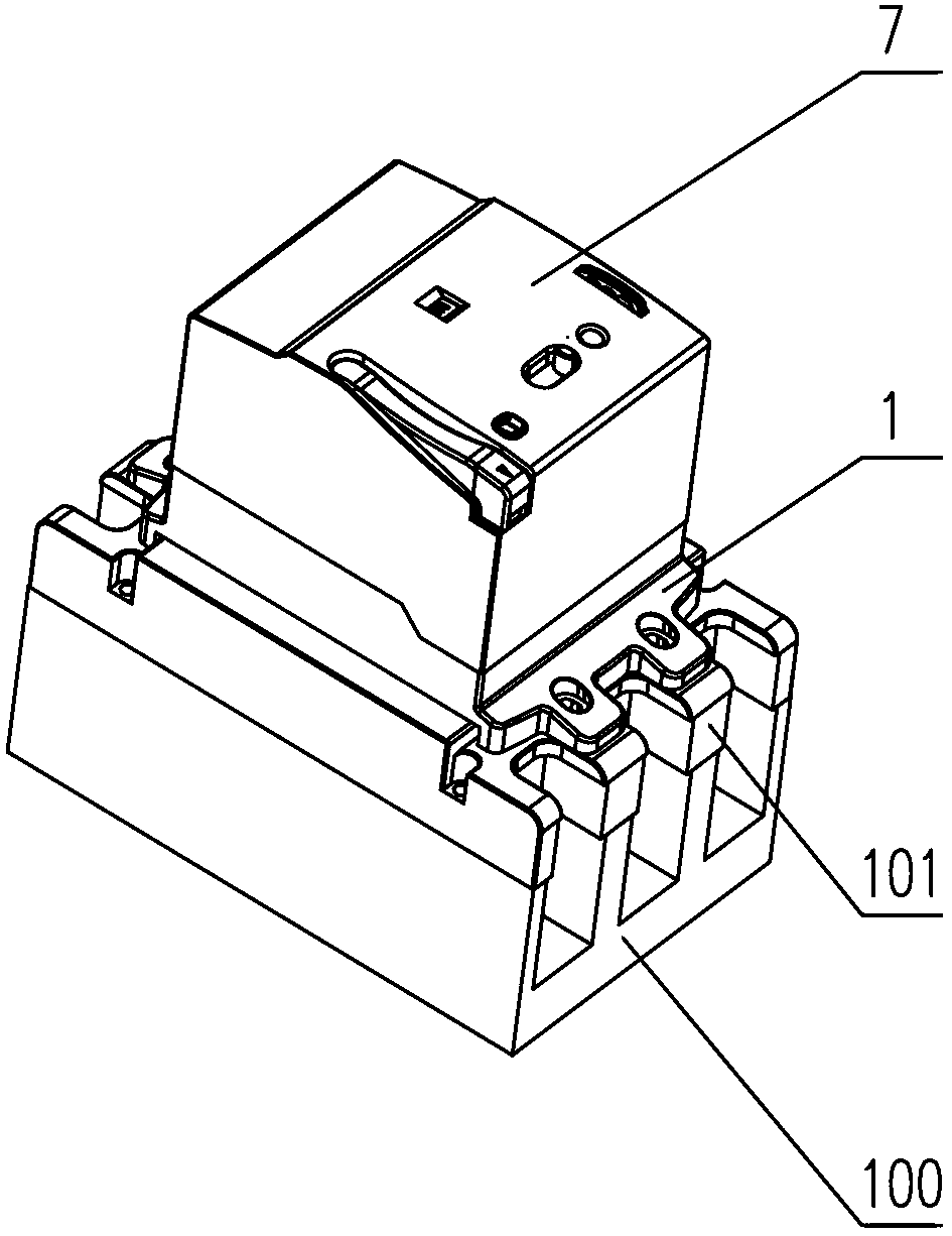
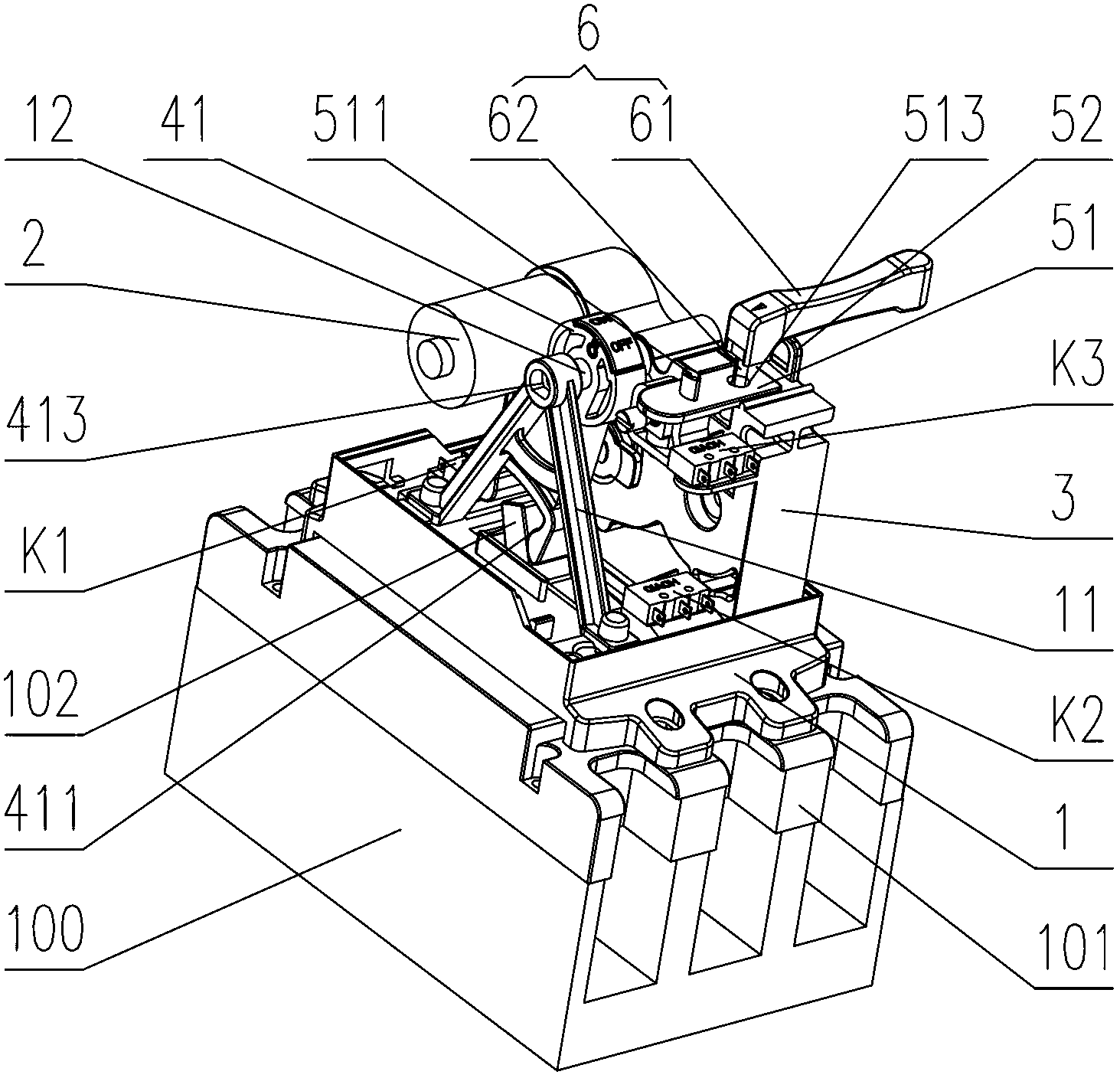
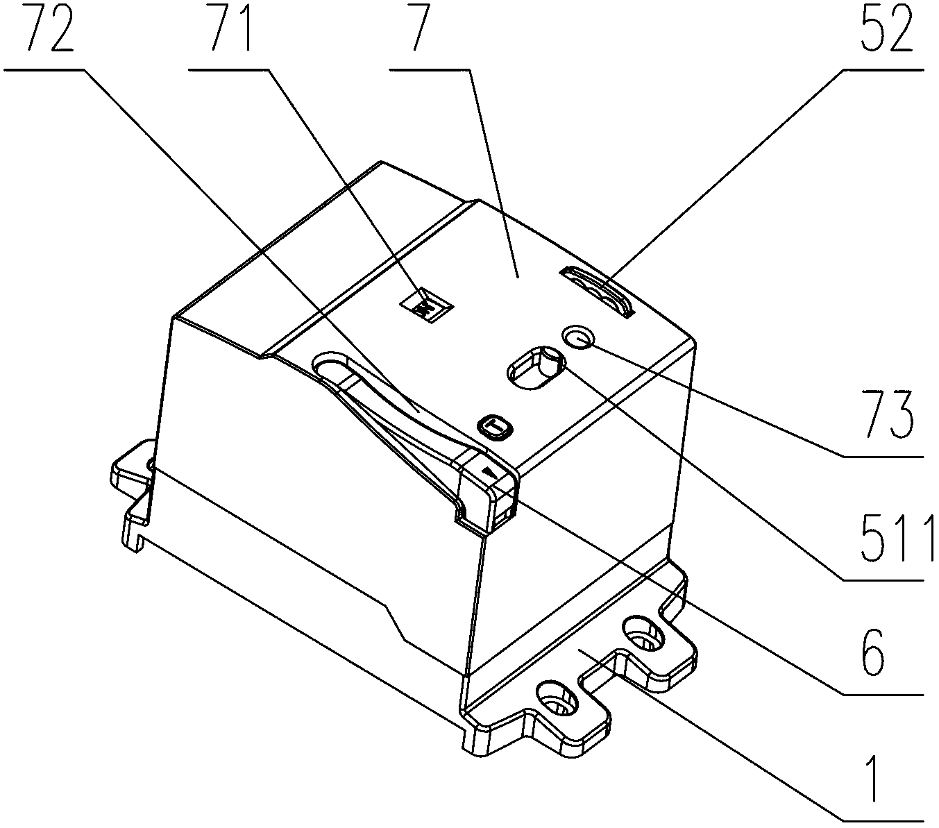
[0032] see Figure 1 to Figure 11 , the electric operating mechanism of the molded case circuit breaker and other isolating switches of the present invention includes a base 1 that can be fixedly installed on the panel 101 of the operated switch 100, and a motor 2, a reducer 3, a driving device 4, and a control device 5. Manual operation handle 6, control panel 7. It is well known that the installation method of the electric operating mechanism will affect the use, function and structural scheme of the electric operating mechanism product. The electric operating mechanism of the present invention adopts the installation method that the base 1 is fixedly connected with the panel 101 of the operated switch 100, ...


PUM


Abstract

The invention relates to an electric operation mechanism of a switch, which is used for remote control and local manual control of a circuit breaker or other bridging switches. A base of the electric operation mechanism is arranged on a panel of a switch. A speed reducer comprises a speed reducer case body, a speed reducing gear set and an output shaft. A driving device comprises a shifting fork with prongs, a rotary shaft of a manual operation handle is inserted from a socket in a control panel to be connected with a steering gear, and the steering gear is engaged with the speed reducing gear set. A first microswitch and a second microswitch are arranged on both sides of a through hole, and the microswitches are touched by the shifting fork to stop powering a motor. The speed reducer case body is vertically arranged on one side of the base, and the speed reducing gear set and the steering gear are positioned in the speed reducer case body. The motor is vertically arranged on the first side surface of the speed reducer case body, an output shaft of the motor extends into the speed reducer case body from the first side surface, and an output shaft of the speed reducer extends out of the first side surface to drive the shifting fork to rotate. The electric operation mechanism has the advantages of compact structure, high space utilization rate, safety, reliability, no vibration or noise and low manufacturing cost.

Description

technical field [0001] The invention relates to an electric operating mechanism of a switch, in particular to an electric operating mechanism for operating a molded case circuit breaker or a disconnector to perform closing and breaking, especially an electric operating mechanism stacked and installed on a panel of a switch. Background technique [0002] Closing and breaking operations of existing molded case circuit breakers and disconnectors are usually manually controlled, requiring personnel to go to the site for manual operation. When the molded case circuit breakers are distributed in a wide range and relatively far away, or the molded case circuit breakers and disconnectors are in dangerous situations or other situations that are not easy to operate, it is necessary to remotely control the closing / breaking of the circuit breakers and disconnectors. With the scientific development of smart grid and power consumption and distribution management based on safety, energy sa...

Claims


Application Information

Patent Timeline
IPC IPC(8): H01H3/26
Inventor 林恒周小林
Owner SHANGHAI GOOD FAITH ICEST
Learn More