
Collision reinforcement material for vehicle

A technology for reinforcing materials and vehicles, applied in vehicle parts, bumpers, doors, etc., can solve problems such as reaction force drop, wall member deformation, weight increase, etc. long lasting effect

Active Publication Date: 2012-11-28
AISIN TAKAOKA CO LTD
View PDF8 Cites 7 Cited by
  • Summary
  • Abstract
  • Description
  • Claims
  • Application Information

AI Technical Summary

Problems solved by technology

[0011] However, in the case of the door impact bar in which the cross-sectional shape in the longitudinal direction from the center to the end is kept constant as in the conventional example, there is a possibility that after a load is input during a side collision, That is, a concentrated load is applied only to the input point of the load, thereby bending at the input point of the load, or deforming the wall member to open outward
Furthermore, there is a disadvantage that after the deformation centered on the input point of the load occurs, the stress concentrates only near the input point of the load to generate a plastic strain (plastic strain), and as a result, the bending rigidity decreases as the rod deforms. drop, and the reaction force drops sharply (see the comparative example described later)
For the previous car door anti-collision bar, in order to make up for the above-mentioned shortcomings, the strength of the car door anti-collision bar must be increased by making the material thicker or making the hat-shaped section larger, which will lead to an increase in manufacturing cost or Adverse conditions such as weight gain

Method used


Image

  • Collision reinforcement material for vehicle
  • Collision reinforcement material for vehicle
  • Collision reinforcement material for vehicle

Examples


example 1

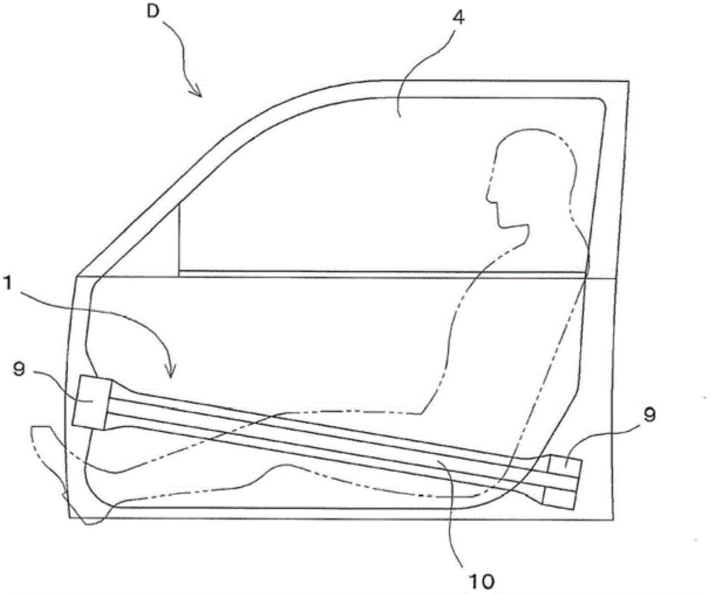
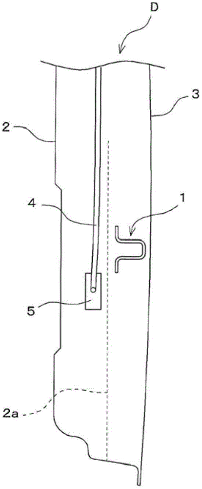
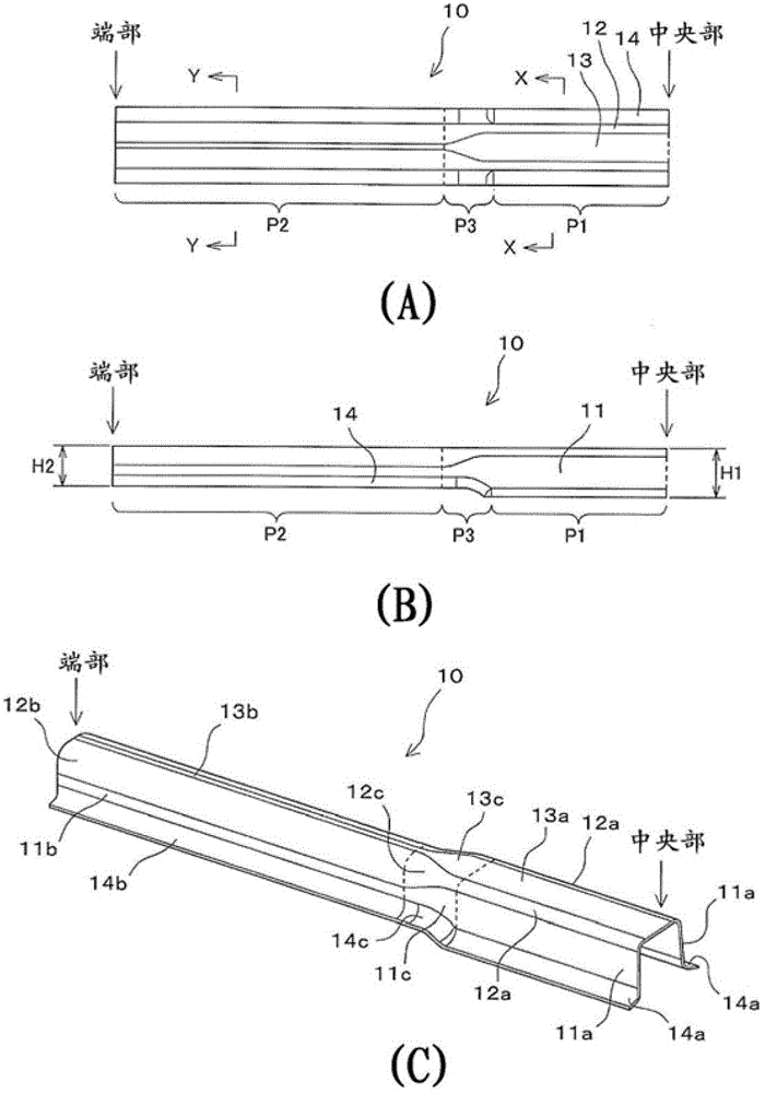
[0058] Such as figure 1 As shown, bracket portions 9 are integrally formed at both ends in the longitudinal direction of the elongated main body portion 10 in the door bumper 1 of Example 1, respectively. image 3 A plan view, a side view, and a perspective view showing the door impact bar 1 in a state in which the main body portion 10 other than the bracket portion 9 is cut from the center. The main body portion 10 of the door bumper 1 includes: a pair of facing wall portions 11 (11a, 11b, 11c); Between the front end portions; a pair of corner (corner) bent portions 12 (12a, 12b, 12c), the front end portion of the wall portion 11 is connected with the central flange portion 13; and a pair of outer peripheral flange portions 14 (14a, 14b, 14c ), from the respective rear ends of the two wall parts 11 to the outward direction ( image 3 (A) up and down direction, Figure 4 left and right direction) stick out. Such as Figure 4 As shown, since a pair of wall portions 11, a c...

example 2

[0076] Figure 9 Example 2 of the present invention is shown. Such as Figure 9 (A)~ Figure 9 As shown in (C), the main body portion of the door bumper bar 20 of Example 2 includes: a central flange portion 33, a pair of corner bending portions 32, a pair of wall portions 31, and a pair of outer peripheral flange portions 34, which are the same as those of Example 1. same. In Example 2, the third portion (gradient portion) P23 of the door impact bar 20 is formed longer than the third portion P3 of Example 1 in the length direction.

[0077] The corner bending portion 32c of the third portion (gradient portion) P23 includes: a fixed-length section adjacent to the second portion P22 and maintaining the same cross-sectional area as the second portion P22; and a remaining section adjacent to the first portion P21 . In the remaining section, the cross-sectional area of ​​the corner bending portion 32c gradually becomes narrower as it approaches the first portion P21.

[0078...

example 3

[0083] Figure 11 Example 3 of the present invention is shown. Such as Figure 11 (A)~ Figure 11 As shown in (C), the main body portion of the door bumper bar 40 of Example 3 includes: a central flange portion 53, a pair of corner bending portions 52, a pair of wall portions 51, and a pair of outer peripheral flange portions 54, which are the same as those of Example 1. same. In Example 3, the third portion (gradient portion) P43 of the door bumper 40 is formed longer than the third portion P3 of Example 1 in the length direction.

[0084] The corner bending portion 52c of the third portion (gradient portion) P43 includes: a section of a fixed length adjacent to the first portion P41 and maintaining the same cross-sectional area as the first portion P41; and a remaining section adjacent to the second portion P42. In the remaining section, the cross-sectional area of ​​the corner bending portion 52c gradually becomes larger as it approaches the second portion P42.

[0085...


PUM

PropertyMeasurementUnit
Thicknessaaaaaaaaaa

Abstract

It is an object of the present invention to provide a crash reinforcing member for a vehicle capable of preventing reduction in flexural rigidity as much as possible even if deformation progresses when a load at the time of crash of the vehicle is input. [Solution] A crash reinforcing member for a vehicle (e.g., door impact beam) includes a long body 10. The body 10 has a hat-shaped opened cross-sectional shape by connecting, with one another, a pair of walls 11, a pair of curved corners 12, a center flange 13, and a pair of outer flanges 14. The body 10 is divided into three sections P1, P2 and P3. A width (C1) of the center flange in the section P1 is wider than a width (C2) of the center flange in the section P2. A cross-sectional area of the curved corner 12 in the section P1 is narrower than a cross-sectional area of the curved corner in the section P2. A cross-sectional height (H1) of the section P1 is higher than a cross-sectional height (H2) of the section P2. The section P3 is provided as a gradually changing portion which smoothly connects the section P1 and the section P2 with each other.

Description

[0001] [reference] [0002] This application claims priority based on Japanese Patent Application (Japanese Patent Application No. 2011-065678) filed with Japan Patent Office on March 24, 2011. technical field [0003] The present invention relates to a vehicle crash reinforcement material, which is installed for the purpose of absorbing energy when a vehicle collides and reducing deformation of the vehicle body toward the inner side of the vehicle. Background technique [0004] As a crash reinforcement material for a vehicle, a door impact beam (also referred to as a door guard) mounted on an inner surface of a door of a vehicle is known. Hitherto, door impact bars in which brackets (mounting fittings) are welded to both end portions of a tubular main body have been widely used. However, in recent years, a door impact bar in which a bar main body and a bracket are integrally press-molded has become mainstream. Among such door impact bars in which the bar body and the brac...

Claims


Application Information

Patent Timeline
IPC IPC(8): B60R19/42
CPCB60J5/0444B60J5/0429B60J5/0461
Inventor 伊藤嘉则
Owner AISIN TAKAOKA CO LTD
Learn More