LED lamp

a technology of led lamps and led tubes, applied in the field of led lamps, can solve the problems of easy production of color unevenness, inevitably produced color unevenness, white light, etc., and achieve the effects of increasing rigidity, reducing cost, and increasing flexural rigidity

Inactive Publication Date: 2006-08-24
PANASONIC CORP
View PDF19 Cites 74 Cited by
  • Summary
  • Abstract
  • Description
  • Claims
  • Application Information

AI Technical Summary

Benefits of technology

[0040] In an LED lamp according to the present invention, the reflector has a framework that is made of a material having a higher flexural rigidity than a resin. Thus, compared to a conventional reflector that is made of a resin only, the reflector of the present invention has significantly increased rigidity. As a result, LED lamps can be manufactured at a reduced cost with their warp minimized.

Problems solved by technology

An LED lamp of this type, however, easily produces color unevenness because the LED chip of each color has an excellent monochromatic peak.
That is to say, unless the light rays emitted from the respective LED chips are mixed together uniformly, color unevenness will be produced inevitably in the resultant white light.
However, the luminous flux of a single LED chip is too low.
However, if the optical reflector 203 is made of a metal, a high patterning cost needs to be paid to cut those openings 203b highly precisely, thus increasing the price of the optical reflector 203.
Nevertheless, if the heat-dissipating substrate 201 were thickened, then it would be difficult to reduce the thickness of the LED lamp 250 that could be used as card LED lamp otherwise.
Likewise, even if a special material were adopted for the reflector in order to increase the strength of the substrate while maintaining an appropriate thickness, the material cost would rise, too.

Method used


Image

  • LED lamp
  • LED lamp
  • LED lamp

Examples


embodiment 1

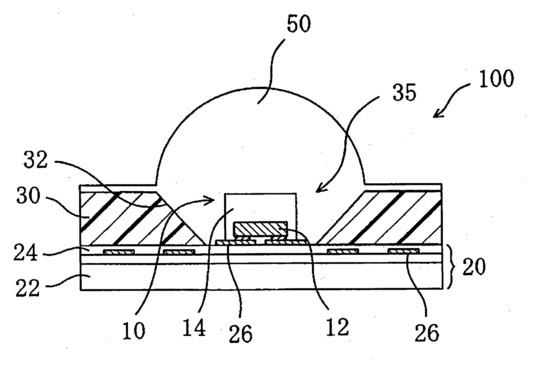
[0056] First, an LED lamp according to a first preferred embodiment of the present invention will be described with reference to FIGS. 3 and 4. A cross-sectional structure of the LED lamp 100 is schematically illustrated in FIG. 3 and a planar layout thereof is schematically illustrated in FIG. 4.

[0057] The LED lamp 100 includes a substrate 20, LED elements 10 that are arranged two-dimensionally on the substrate 20, and a reflector 30 with reflective surfaces 32 for reflecting the emissions of the LED elements 10.

[0058] The reflector 30 may be implemented as a plate resin layer including a framework 40 inside. This resin layer has a plurality of openings, each of which is arranged so as to surround the side surfaces of its associated LED element 10. The framework 40 is made of a material that has a higher flexural rigidity than that of the resin layer of the reflector 30, thereby minimizing the warp of the substrate 20. The framework 40 is preferably made of at least one of a meta...

embodiment 2

[0086] Next, a second preferred embodiment of an LED lamp according to the present invention will be described with reference to FIG. 9.

[0087]FIG. 9 illustrates an LED lamp including a framework 40 in the shape of a cross. The framework 40 shown in FIG. 9 includes a first bar member 40a extending in the row direction parallel to the upper surface of the substrate 20 and a second bar member 40b extending in the column direction parallel to the upper surface of the substrate 20. The first and second bar members 40a and 40b may either form two integral parts of the single framework 40 or be a combination of two separate members. Optionally, the height (or the level) of the first bar member 40a as measured from the upper surface of the substrate 20 may be different from that of the second bar member 40b as measured from the same surface of the substrate 20 and the first and second bar members 40a and 40b may cross each other. In that case, the two bar members 40a and 40b that cross eac...

embodiment 3

[0088] Next, a third preferred embodiment of an LED lamp according to the present invention will be described with reference to FIG. 10.

[0089] The framework 40 shown in FIG. 10 has a lattice shape, which is formed by a first set of bar members 40a and a second set of bar members 40b. In the example illustrated in FIG. 10, two bar members 40a of the first set cross two bar members 40b of the second set. However, depending on the arrangement of LED elements 10, an arrangement in which a greater number of bar members 40a and 40b cross each other may also be adopted.


PUM


Abstract

An LED lamp 100 according to the present invention includes: a substrate 20 with an upper surface; a plurality of LED chips 10, which are arranged on the upper surface of the substrate 20; and a reflector 30, which has reflective surfaces that reflect emissions of the respective LED chips 10 at least partially. The reflector 30 includes a resin and a framework that is made of a material having a higher flexural rigidity than the resin.

Description

[0001] This is a continuation of International Application PCT / JP2005 / 000654, with an international filing date of Jan. 20, 2005, which claims priority of Japanese Patent Application No. 2004-021062, filed on Jan. 29, 2004, the contents of which are hereby incorporated by reference.BACKGROUND OF THE INVENTION [0002] 1. Field of the Invention [0003] The present invention relates to an LED lamp and more particularly relates to an LED lamp that can be used effectively as a white light source for general illumination. [0004] 2. Description of the Related Art [0005] A light emitting diode (which will be referred to herein as an “LED chip”) is a semiconductor device that can radiate an emission in a bright color with high efficiency even though its size is small. The emission of an LED chip has an excellent monochromatic peak. To produce white light from LED chips, a conventional LED lamp arranges red, green and blue LED chips close to each other and gets the light rays in those three dif...

Claims


Application Information

Patent Timeline
Patent Type & Authority Applications(United States)
IPC IPC(8): H01L33/00F21S2/00F21S8/04F21V7/00F21V7/10F21V7/22F21Y101/02H01L33/32H01L33/48H01L33/50H01L33/54H01L33/56H01L33/60H01L33/62
CPCF21K9/00H01L33/60F21Y2101/02F21Y2105/001H01L2224/13H01L2224/48091H01L2224/8592H01L2224/48247H01L2224/49107H01L2924/00014F21Y2105/10F21Y2115/10H01L2924/181H01L2224/48257F21K9/68H01L2924/00011H01L2224/0401H01L2924/00012
Inventor YANO, TADASHISHIMIZU, MASANORITAKAHASHI, KIYOSHIKANAYAMA, YOSHIHIKO
Owner PANASONIC CORP
Why Eureka
Try Eureka