Method and filling installation for filling a hydrogen gas into a vessel

A technology for containers and hydrogen, which is applied in the equipment for loading pressure vessels, filling methods for containers, and installation devices for container structures, etc., can solve the problems of uncontrolled hydrogen temperature, gas outflow, and loss of precious gas.

Inactive Publication Date: 2012-11-28
TEESING
View PDF8 Cites 0 Cited by
  • Summary
  • Abstract
  • Description
  • Claims
  • Application Information

AI Technical Summary

Problems solved by technology

Intense pre-cooling gas can cause problems with freezing of connected grease nipples
Moreover, the temperature of the hydrogen in the vehicle's on-board gas storage tank cannot be controlled
The temperature of the hydrogen needs to be low enough to allow the gas storage tank to achieve the desired filling rate, but w

Method used


Image

  • Method and filling installation for filling a hydrogen gas into a vessel
  • Method and filling installation for filling a hydrogen gas into a vessel
  • Method and filling installation for filling a hydrogen gas into a vessel

Examples


Embodiment Construction

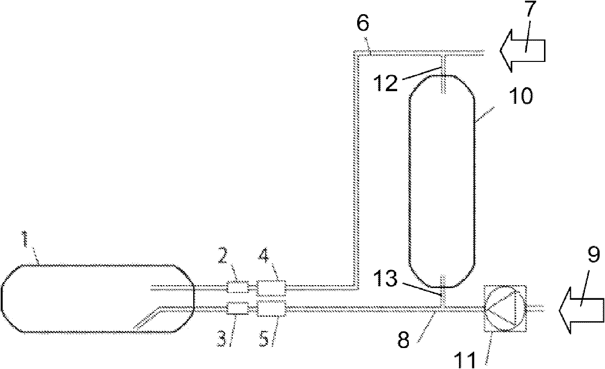
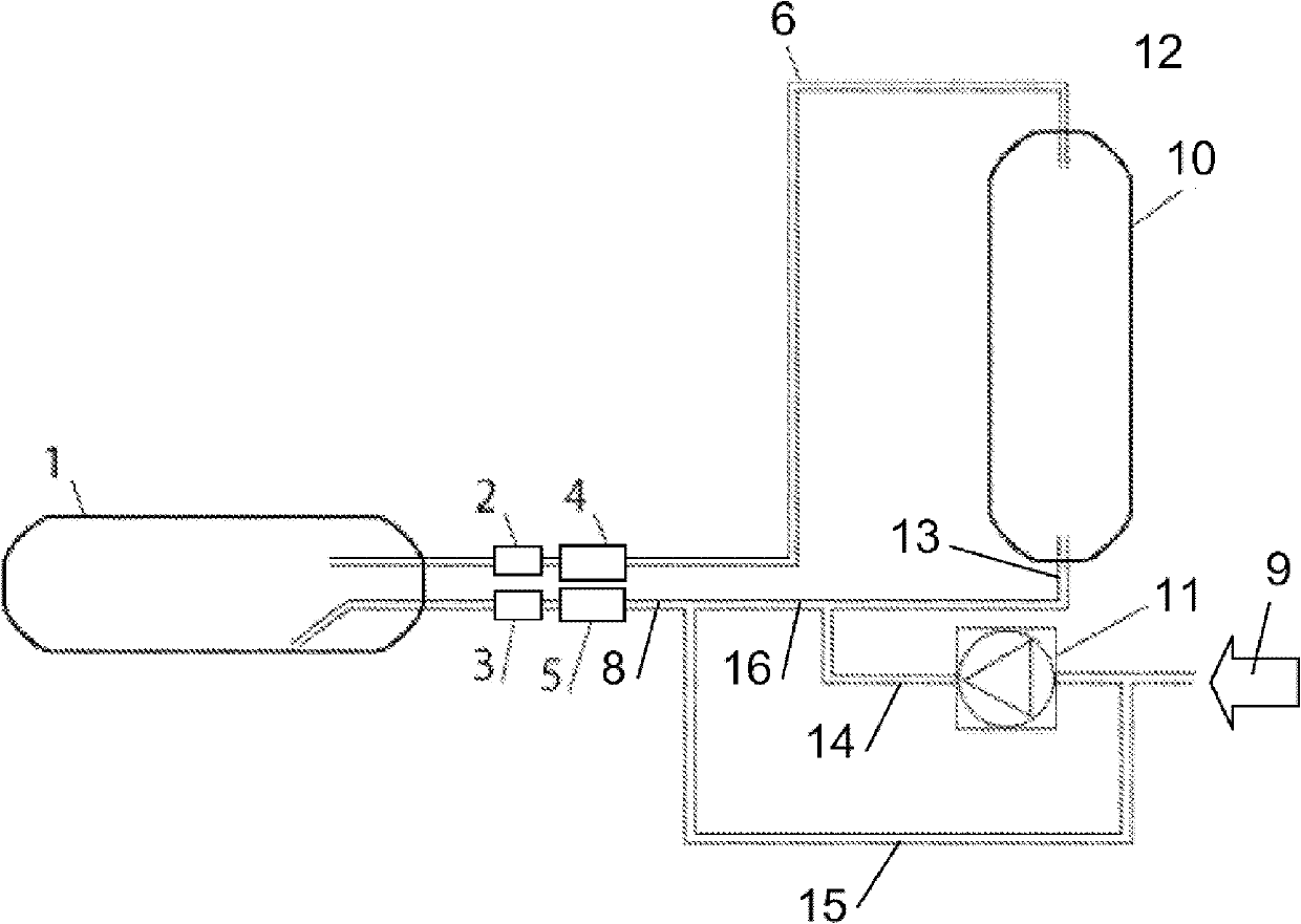
[0037] In the drawings, the same components or components with similar functions are denoted by the same reference numerals.

[0038] In the present description and claims, the term "container" includes all types of storage containers that hold hydrogen gas or fluid in liquid form at a pressure different from the ambient pressure.

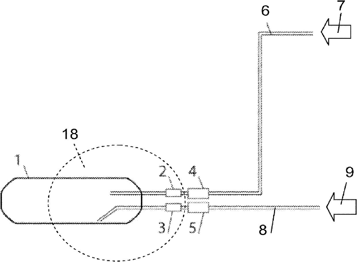
[0039] figure 1 It is a schematic diagram of a container 1, such as a hydrogen fuel storage tank or a hydrogen cylinder installed in a vehicle. The container 1 has a first port 2 for gas to pass through and a second port 3 for liquid to pass through, wherein the second port 3 is connected to the The first port 2 is separated from which, in the embodiment shown, the second port 3 is separated by a large or remote distance.

[0040] Such as figure 1 As shown, when the container 1 is placed in the working position, the second port 3 terminates in the container 1 , preferably below the end of the first port 2 located in the container 1 . The two por...


PUM


Abstract

The invention discloses a method and a filling installation for filling a hydrogen gas into a vessel (1) having a first port (2) for passing the hydrogen gas and a second port (3) for passing a fluid, wherein the second port (3) is separate from the first port (2). In a first phase a hydraulic fluid is introduced into the vessel (1) through the second port (3) by applying pressure to the hydraulic fluid, such that the hydraulic fluid in the vessel (1) causes a hydrostatic pressure having a pre-determined value. In a second phase the hydrogen gas is introduced into the vessel (1) through the first port (2) by controlling a difference of pressure relative to a current pressure in the vessel (1) for controlling expansion of the hydrogen gas and thereby temperature inside the vessel (1), such that the vessel (1) is filled with the hydrogen gas. To that end the hydraulic fluid is removed from the vessel (1) through the second port (3).

Description

technical field [0001] The present invention relates to a method of filling hydrogen into a container, such as a vehicle fuel storage tank, having a first port for passage of gas and a second port for passage of liquid, wherein the second port is connected to the The first port is separated, in particular the second port is separated from the first port by a large or remote distance. Background technique [0002] US patent specification US-B1-6,439,278 discloses a compressed natural gas filling system comprising rows of connected elongated cylinders for delivering compressed natural gas to a filling station. Each cylinder has separate ports at one end for CNG and hydraulic fluid that does not mix easily with CNG. A hydraulic fluid port comprises a tube within a cylinder that leads from one end to a point adjacent the other end of the cylinder. In use, hydraulic fluid is introduced into the cylinder through the hydraulic fluid port under pressure, forcing the compressed nat...

Claims


Application Information

Patent Timeline
IPC IPC(8): F17C5/06
CPCY02E60/321F17C2250/0434F17C2250/0631F17C2260/025F17C2227/0192F17C5/06F17C2223/035F17C2225/036F17C2250/043F17C2265/065F17C2205/013F17C2221/033F17C2221/012F17C2265/025F17C2270/0184F17C2250/0443F17C2223/0123F17C2250/0626F17C2260/023F17C2250/032F17C2225/0123F17C2205/0142F17C2270/0168Y02E60/32F17C2225/03
Inventor H·德仲斯特
Owner TEESING
Why Eureka
Try Eureka