Valve timing changing device

A timing change device and gas distribution technology, which is applied to valve devices, non-mechanically actuated valves, output power, etc., can solve the problem of unlocking the locking mechanism or locking cannot work normally, increased processing costs, complex structures, etc. question

Inactive Publication Date: 2012-12-05
MIKUNI CORP
View PDF8 Cites 6 Cited by
  • Summary
  • Abstract
  • Description
  • Claims
  • Application Information

AI Technical Summary

Problems solved by technology

[0007] In this way, in the case of directly using the working oil in the advanced angle chamber and the retarded angle chamber, it is easy to be affected by the hydraulic pressure of the working oil in the advanced angle chamber and the retarded angle chamber, and there is a possibility

Method used


Image

  • Valve timing changing device
  • Valve timing changing device
  • Valve timing changing device

Examples


Embodiment Construction

[0117] Hereinafter, embodiments of the present invention will be described with reference to the drawings.

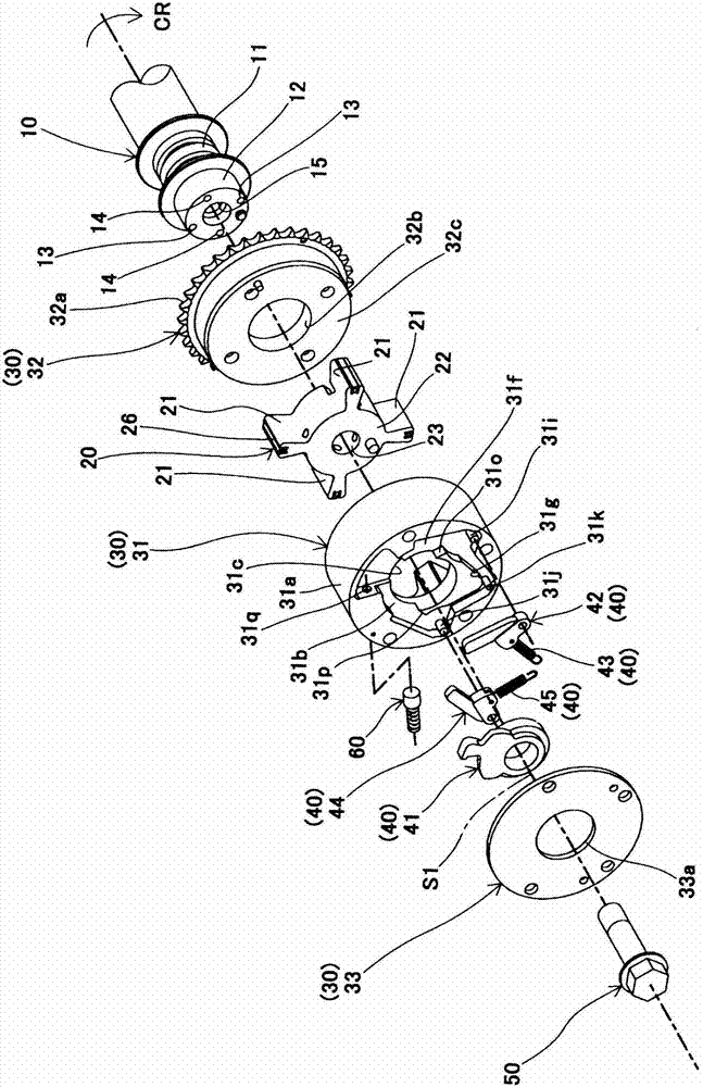
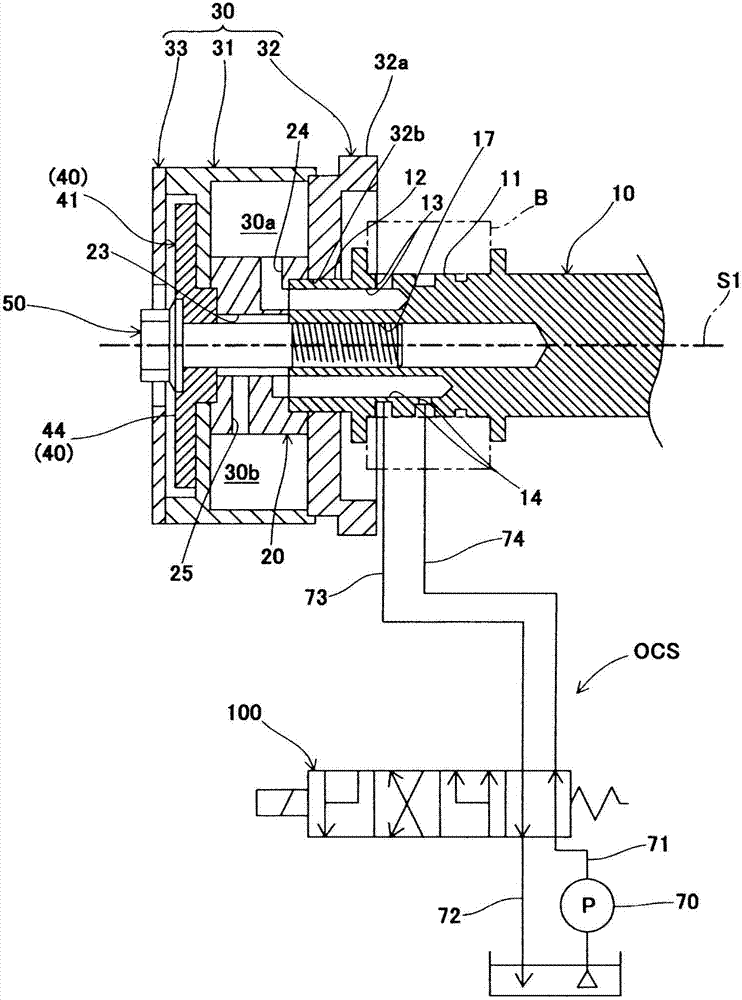
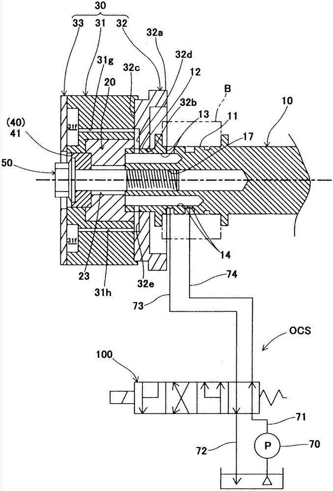
[0118] Such as Figure 1 to Figure 3 As shown, the valve timing changing device includes the following components: the vane rotor 20 is detachably fixed to the camshaft 10; the housing rotor 30 rotates on the axis S1 of the camshaft 10 and The vane rotor 20 is accommodated to be able to rotate relatively, and the casing rotor 30 and the vane rotor 20 together define an advance angle chamber 30a and a lag angle chamber 30b; the locking mechanism 40 (locking cam 41, advance angle lock lever 42, advance angle Limiting spring 43, lagging angle locking lever 44, lagging angle limiting spring 45), which are arranged in the isolation chamber of the housing rotor 30, so as to lock the vane rotor 20 at a predetermined intermediate position relative to the housing rotor 30; the central bolt 50, It fastens the vane rotor 20 to the camshaft 10; the auxiliary mechanism 60 assists i...


PUM


Abstract

The invention provides a valve timing changing device, by which a vane rotor is kept at a central position when the engine is started to prevent sloshing, knocking noise and wearing. The device includes a housing rotor (30), a vane rotor (2), an advance angle passageway (13) communicated with an advance angle chamber for operating oil to pass through, a lag angle passageway (14) communicated with a lag angle chamber for the operating oil to pass through, and a lock mechanism (40) which locks the vane rotor at a center position relative to the housing rotor and unlocks the lock by means of the hydraulic pressure of the operating oil. The lock mechanism includes an advance angle lock bar (42) and a lag angle lock bar (44). The advance angle passageway (13) guides the hydraulic pressure to unlock the lock of the advance angle lock bar and the lag angle lock bar, and the lag angle passageway (14) guides the hydraulic pressure to maintain the unlocking of the lock of the lag angle lock bar. The vane rotor is kept at the central position when the engine is started so as to ensure the stable starting performance of the engine.

Description

technical field [0001] The present invention relates to a valve timing changing device for changing the opening and closing timing (distribution timing) of an intake valve or an exhaust valve of an internal combustion engine according to operating conditions. Background technique [0002] It is known that a conventional valve timing changing device includes the following components, etc.: a casing rotor (casing, external rotor, etc.) that rotates synchronously with the crankshaft; The vane rotor rotates synchronously with the camshaft and is housed in the housing rotor, the housing chamber of the vane rotor is divided into two parts, a retarded angle chamber and an advanced angle chamber, and the vane rotor can be moved relative to the housing. The rotor rotates relatively in a predetermined angle range (between the most advanced angle position and the most retarded angle position); the locking mechanism (locking pin and spring, locking body and spring, etc.) locking the va...

Claims


Application Information

Patent Timeline
IPC IPC(8): F01L1/34F01L9/02F02D13/02F01L9/10
CPCY02T10/18
Inventor 斋藤匡一菅野弘二中西良浦野贵裕
Owner MIKUNI CORP
Why Eureka
Try Eureka