Floating mechanism for main shaft of double countershaft transmission

A technology of double intermediate shafts and floating mechanism, which is used in mechanical equipment, transmission parts, belts/chains/gears, etc., can solve the problems of difficult assembly, easy jamming of hinged ball joints, scattered structure of floating mechanism, etc. Pre-adjustment, easy assembly, simple structure effect

Active Publication Date: 2016-03-16
SINO TRUK JINAN POWER
View PDF5 Cites 0 Cited by
  • Summary
  • Abstract
  • Description
  • Claims
  • Application Information

AI Technical Summary

Problems solved by technology

[0002] In the existing double countershaft transmission, in order to overcome the uneven load of the two auxiliary shaft assemblies, the main shaft must have a float. At present, the rear end of the main shaft is either rigidly connected, or the structure of the floating mechanism at the rear end of the main shaft is scattered. The existing technical solution closest to this The technology is: the publication number is 201103674, and the patent name is: a utility model patent for a floating structure for a transmission. Stuck, causing the spindle to break due to sticking

Method used


Image

  • Floating mechanism for main shaft of double countershaft transmission
  • Floating mechanism for main shaft of double countershaft transmission
  • Floating mechanism for main shaft of double countershaft transmission

Examples


Embodiment Construction

[0017] In order to clearly illustrate the technical features of the solution, the solution will be described below through a specific implementation manner.

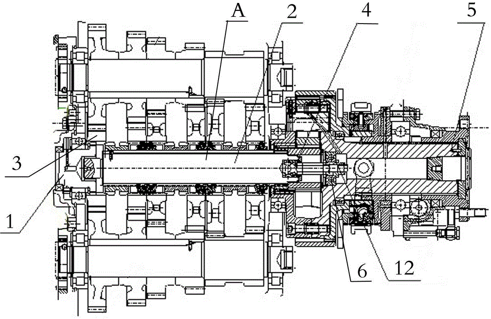
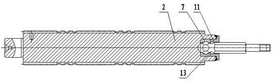
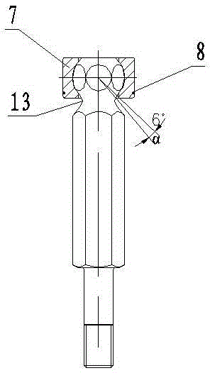
[0018] As shown in the accompanying drawings, a floating mechanism for the main shaft of a double countershaft transmission includes a main shaft 2 connected to the input shaft 1, a floating gap is provided between the front end of the main shaft 2 and the bushing 3 of the input shaft 1, and the main shaft 2 The end is fixedly installed on the bearing 6 on the output shaft 5 through an integral joint bearing unit 4. The integral key bearing unit 4 includes a bearing outer ring 7, a self-locking spring 8, and a ball stud. The bearing outer ring 7 is located at In the inner hole of the main shaft, the bearing outer ring 7 includes two hemispheres split along the axis, and the two hemispheres are fixedly connected as a whole by a self-locking spring 8. The ball cavity of the bearing outer ring 7 is installed with The ball h...


PUM


Abstract

A floating mechanism for a spindle of a transmission with double intermediate shafts comprises the spindle connected with an input shaft. The tail end of the spindle is fixedly mounted on a bearing of an output shaft through an integral knuckle bearing unit; the integral knuckle bearing unit comprises a bearing outer ring, a self-locking spring and a ball joint rod; the bearing outer ring is positioned in an inner hole of the spindle and comprises two hemispheres which are separated from each other along an axis; the two hemispheres are fixedly connected integrally through the self-locking spring; a ball joint of the ball joint rod is mounted in a ball cavity of the bearing outer ring; the bearing outer ring is axially positioned through a knuckle bearing pressing ring; the knuckle bearing pressing ring is fixedly welded with an end of the spindle along a circumference; a rod body of the ball joint rod is connected with the output shaft through a locking nut in an axially positioned manner. The floating mechanism has the advantages that the bearing outer ring and the ball joint rod are assembled into an integral unit structure, and the floating mechanism is simple in structure and convenient to assemble, is not required to be adjusted, and can float flexibly, and the spindle can be accurately positioned axially.

Description

technical field [0001] The invention relates to a floating mechanism for a main shaft of a double intermediate shaft transmission. Background technique [0002] In the existing double countershaft transmission, in order to overcome the uneven load of the two auxiliary shaft assemblies, the main shaft must have a float. At present, the rear end of the main shaft is either rigidly connected, or the structure of the floating mechanism at the rear end of the main shaft is scattered. The existing technical solution closest to this The technology is: the publication number is 201103674, and the patent name is: a utility model patent for a floating structure for a transmission. Stuck, causing the spindle to break due to sticking. Contents of the invention [0003] Aiming at the deficiencies of the prior art, the present invention provides a technical scheme of a floating mechanism for a main shaft of a double countershaft transmission with simple structure, easy assembly and fle...

Claims


Application Information

Patent Timeline
Patent Type & Authority Patents(China)
IPC IPC(8): F16H57/021
Inventor 石红云王颖颖陶磊
Owner SINO TRUK JINAN POWER
Why Eureka
Try Eureka