
Detecting method and detecting device for rigged dynamic weighing of vehicle

A technology of dynamic weighing and detection methods, which is applied in the direction of measuring devices, weighing, instruments, etc., can solve the problems of evidence storage and dispute resolution that cannot be truly avoided, single source of evidence, and complex vehicle conditions, etc.

Active Publication Date: 2012-12-05
BEIJING WANJI TECH
View PDF5 Cites 30 Cited by
  • Summary
  • Abstract
  • Description
  • Claims
  • Application Information

AI Technical Summary

Problems solved by technology

[0035] However, although the above weighing data cheating analysis method can well complete the judgment and compensation for cheating driving of the vehicle, it cannot really avoid the settlement of evidence and disputes. The downsides of the way analytics and algorithmic compensation are done are:
[0036] (1) There is a high possibility of disputes. Even if the vehicle under test is driving in violation of regulations, the data collected by the vehicle dynamic weighing system can accurately determine and compensate for the lost weight
However, due to the fact that there is only evidence in the data, some drivers refuse to accept punishment by denying and other means, which makes management more difficult and disputes continue.
[0037] (2) It is difficult to store certificates. In practical applications, the site where the vehicle is weighed is often in complex conditions. The wheels of the vehicle may randomly stop, start or reverse on the weighing platform, and the axle may jump on the weighing platform. If the whole process of S-type driving cannot be stored through video and played back through the system, there will be dead ends in the management of punishment for some drivers
[0038] (3) The basis for detection and punishment is too single. At this stage, the anti-cheating method only relies on the weight data collected when the vehicle passes through dynamic detection for punishment and compensation. Not only is the evidence not strong, but the source of evidence is single

Method used


Image

  • Detecting method and detecting device for rigged dynamic weighing of vehicle
  • Detecting method and detecting device for rigged dynamic weighing of vehicle
  • Detecting method and detecting device for rigged dynamic weighing of vehicle

Examples


Embodiment 1

[0067] Figure 7 It is a schematic structural diagram of a vehicle dynamic weighing cheating detection device according to an embodiment of the present invention; the vehicle dynamic weighing cheating detection device includes: a video camera 201, a supplementary light (not shown in the figure), an information display screen 202, and an outdoor sound and light alarm Device 203, indoor voice prompter 204 and data processing industrial computer 205. Indoor voice prompter 204 and data processing industrial computer 205 are installed in toll booth 206 .

[0068] The video camera 201 is used to detect the video image during the dynamic weighing process of the vehicle. It is installed at a distance of 6 meters from the weighing platform. The video center point is located 1 meter in front of the weighing platform. The supplementary light is used for light compensation of the vehicle at night. To facilitate the video camera 201 to shoot.

[0069] The data processing industrial compute...

Embodiment 2

[0071] Such as Figure 8 As shown, this embodiment provides a method for detecting cheating in vehicle dynamic weighing, and the method for detecting cheating in vehicle dynamic weighing includes:

[0072] Step S801: Collecting images of the driving state of the inspected vehicle. A video camera 201 (high-definition / standard-definition camera) is used to collect images of the driving state of the inspected vehicle.

[0073] Step S802: Obtain trajectory information of a specific part of the inspected vehicle from the driving state image.

[0074] The video captured by the video camera 201 is uploaded to the data processing industrial computer 205 through the network cable. The data processing industrial computer 205 obtains the local trajectory information of the inspected vehicle from the driving state image, such as the trajectory information of the license plate, vehicle lights, and body contours. The present invention takes the trajectory information of a certain point on...

Embodiment 3

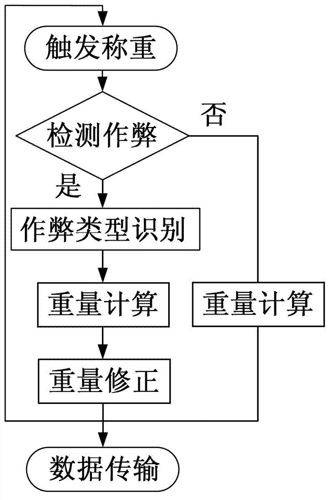
[0150] The above-mentioned embodiment 2 detects whether the vehicle is running normally and the type of abnormal driving by analyzing the video image. Although it can detect whether the vehicle is running normally, there is a possibility of misjudgment only by analyzing the video image to detect the vehicle. For example, for Table 6 In the case where the true value is 0 in Table 6, and the other true values ​​are all 0, it is judged to be traveling at a variable speed, and the judgment result may not be accurate. In order to further provide the judging result of the vehicle driving state, the present invention combines the waveform data analysis in the prior art with the video image analysis, adopts two scoring mechanisms for analysis, obtains a more accurate judging result, and generates the vehicle under inspection For final driving status, please refer to Figure 11 . Also included based on specific instructions are the following:

[0151] Step 1: Select |Δ from the 1st t...


PUM


Abstract

The invention provides a detecting method and detecting device for rigged dynamic weighing of a vehicle. The detecting method comprises the following steps: acquiring an image of a running state of a detected vehicle; obtaining track information of a specific part of the detected vehicle from the image of the running state; generating state information of the vehicle based on the track information, wherein the state information of the vehicle include an average speed Vave, a distance difference delta l of two adjacent frames, a displacement distance difference delta y, and a linear model; and determining the running state of the detected vehicle based on the pre-stored speed deviation threshold Vl, linear deviation threshold xl, distance deviation threshold yl of adjacent frames, intermediate left deviation threshold xmin, intermediate right deviation threshold ymax and the state information of the vehicle.

Description

technical field [0001] The invention relates to a technology for judging cheating driving behavior in the process of vehicle weighing, especially for vehicle dynamic weighing technology on highways and other roads, and specifically a method and device for detecting cheating in vehicle dynamic weighing. Background technique [0002] In recent years, since the gradual implementation of truck weight charges, more and more freight drivers are driven by interests, aiming at the characteristics of dynamic weighing of weighing equipment, and adopt illegal driving methods to avoid normal payment, including: S-type weighing, There are various forms such as skipping weighing, high-speed punching, pressing and weighing. It will greatly affect the fairness of weight-based charging transactions, and cause great damage to weighing equipment and other road facilities due to excessive driving and overloading. [0003] In the existing technology, the anti-cheating of the vehicle during the ...

Claims


Application Information

Patent Timeline
IPC IPC(8): G01G19/03
Inventor 张佳贺成瑜娟陈峰
Owner BEIJING WANJI TECH
Learn More